Hardware Design of Location Anchor
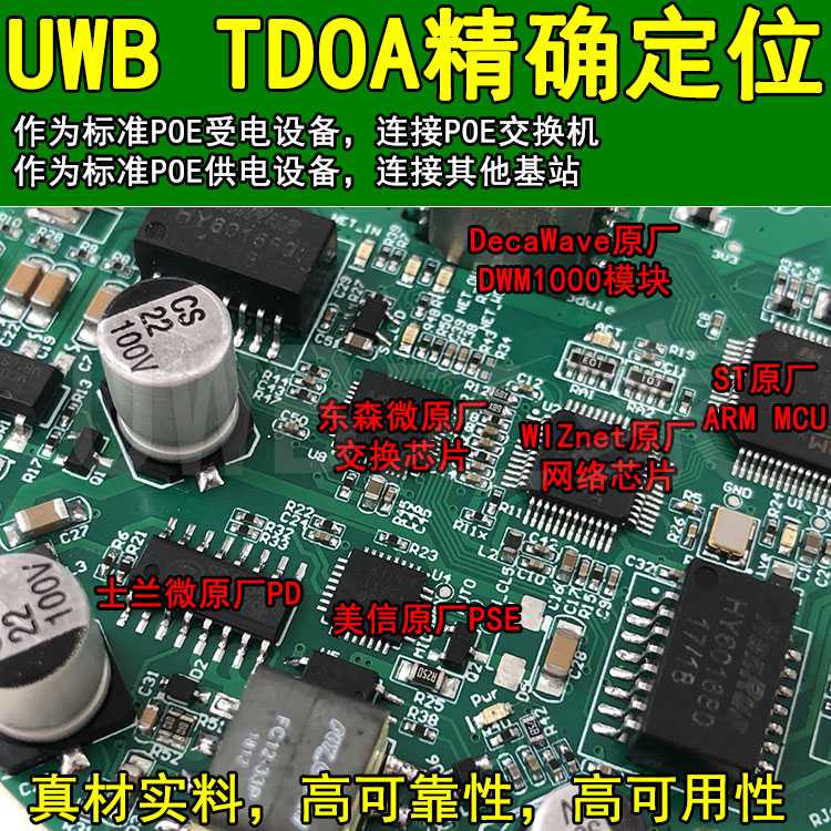
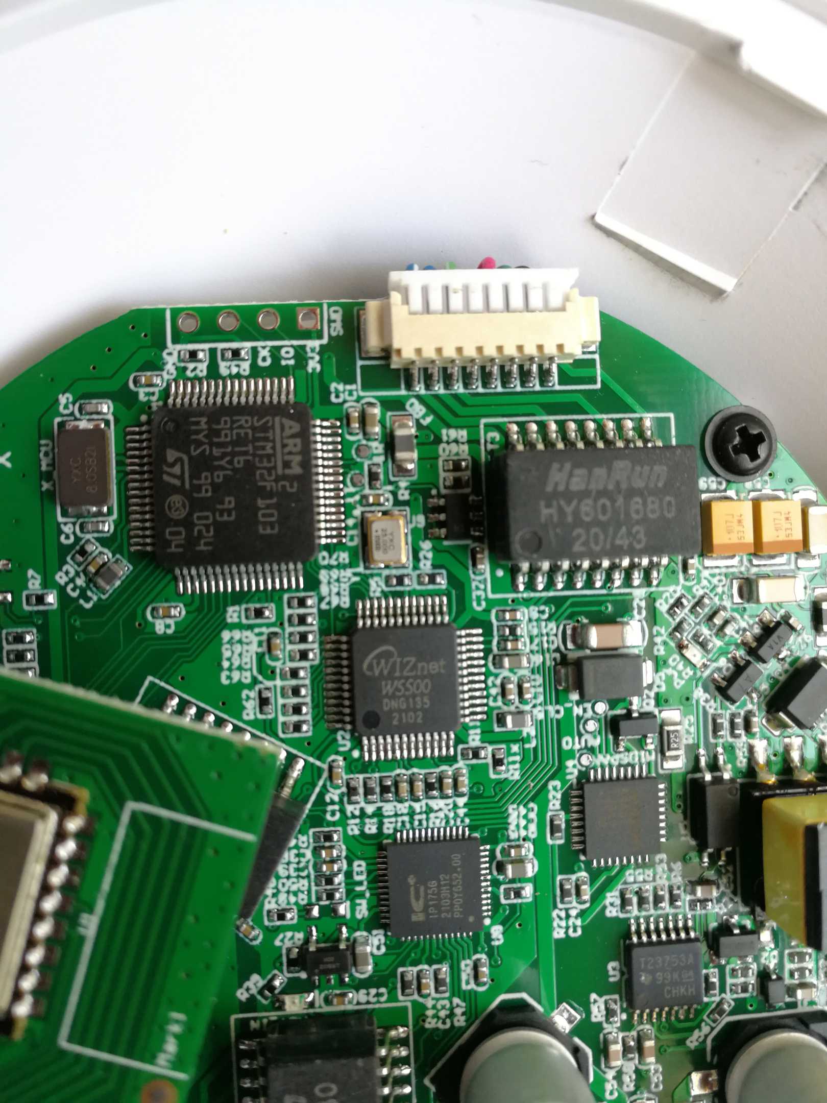
The main control of the location anchor is STM32F103RET6. This MCU has a relatively large Flash and a relatively large RAM, and is suitable for running RTOS.
The UWB transceiver of the anchor uses the DW1000 chip. We directly used the DWM1000 module in the early stage, because the DWM1000 module has already completed the radio frequency part and provides some SPI interfaces to the outside world. We do not need to worry about the analog part of the circuit and can just focus on the logic circuit. Later, some anchor types were added, and some changes were made in this part. Several new designs were added: (1) Making your own modules similar to DWM1000 can save costs; (2) Your own UWB modules use ceramic antennas or PCB antennas, and there are also IPX The base lead uses an external high-gain underline; (3) Add PA/LNA. The original communication distance can reach up to 300 meters at the rate of 850K, and it can reach more than 1000 meters after adding PA/LNA.
The network interface chip uses W5500. This chip uses SPI interface and the network speed is 100M. In fact, judging from the amount of UWB data, 100M is too much, and 10M is enough.
There are two designs for the power supply: (1) using POE power supply, which is used in major mass production models; (2) using DC-DC to convert 12V to 3.3V for use by on-board devices, which is used in the initial prototype and Used upon request by some OEM customers.
We also have a model of anchor that integrates a network switch chip and POE power supply. Multiple anchors can be cascaded and strung together to save wiring costs.
The research and development process of the anchor goes through several stages.
The first stage is experimental in nature.
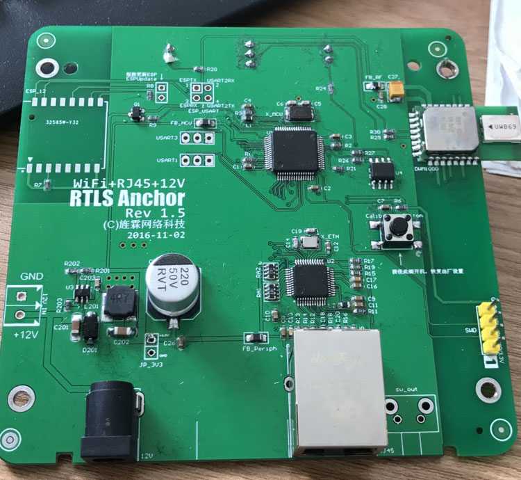
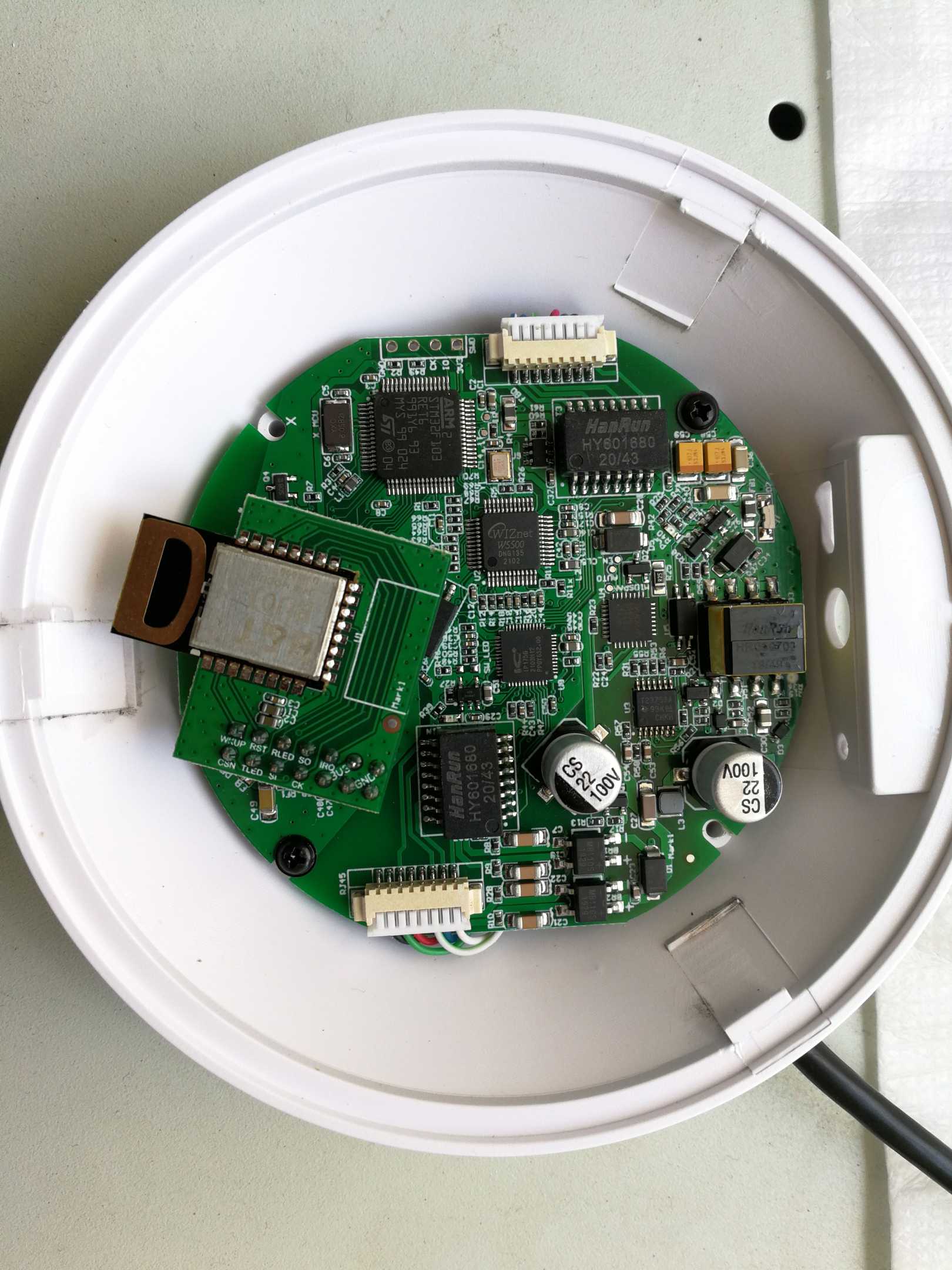
As you can see from the picture above, during the design, the network not only supports Ethernet (RJ45 interface), but also supports WIFI and uses 12V power supply. WIFI uses the ESP8266 module. A large box is used for the casing.
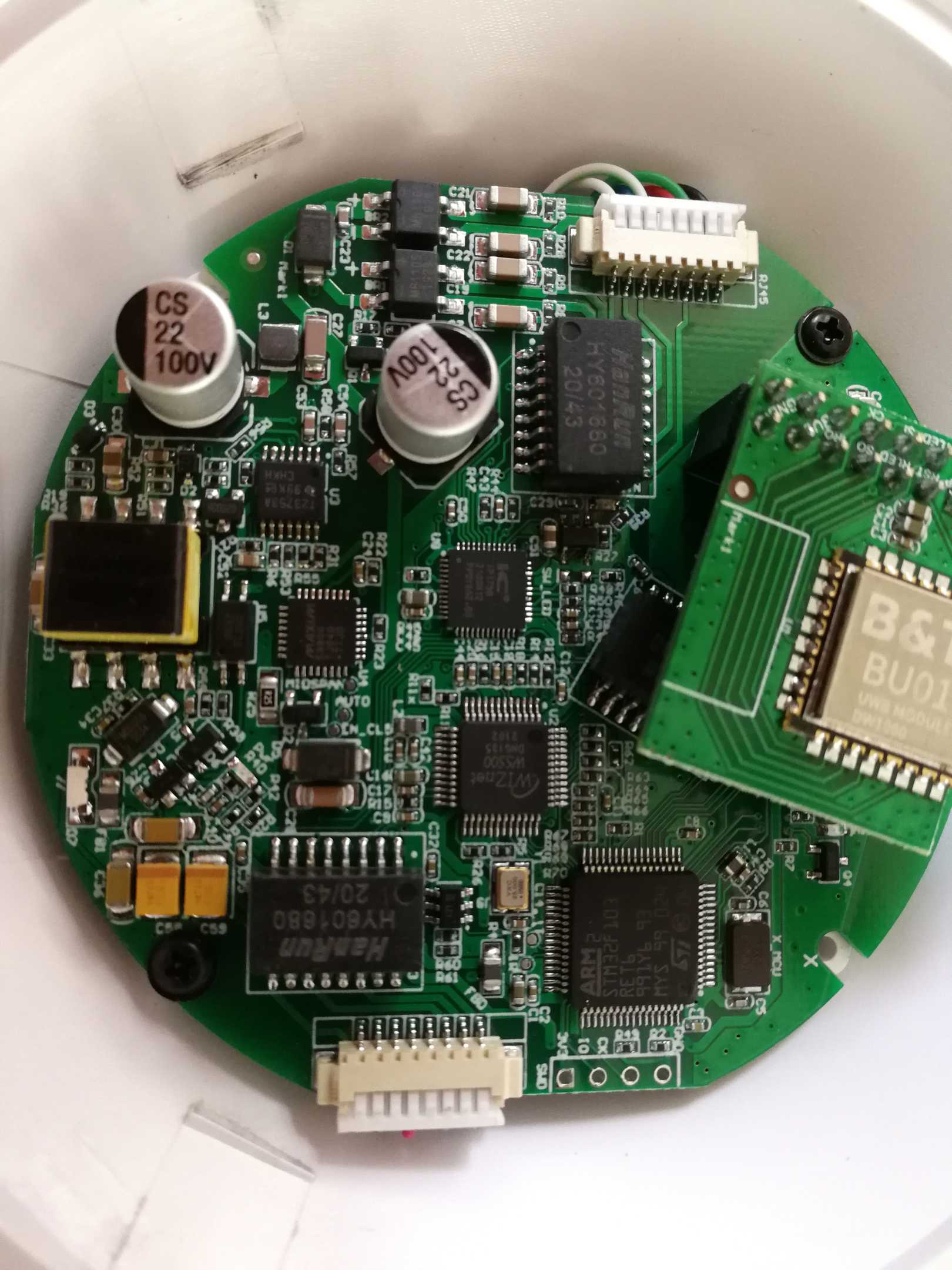
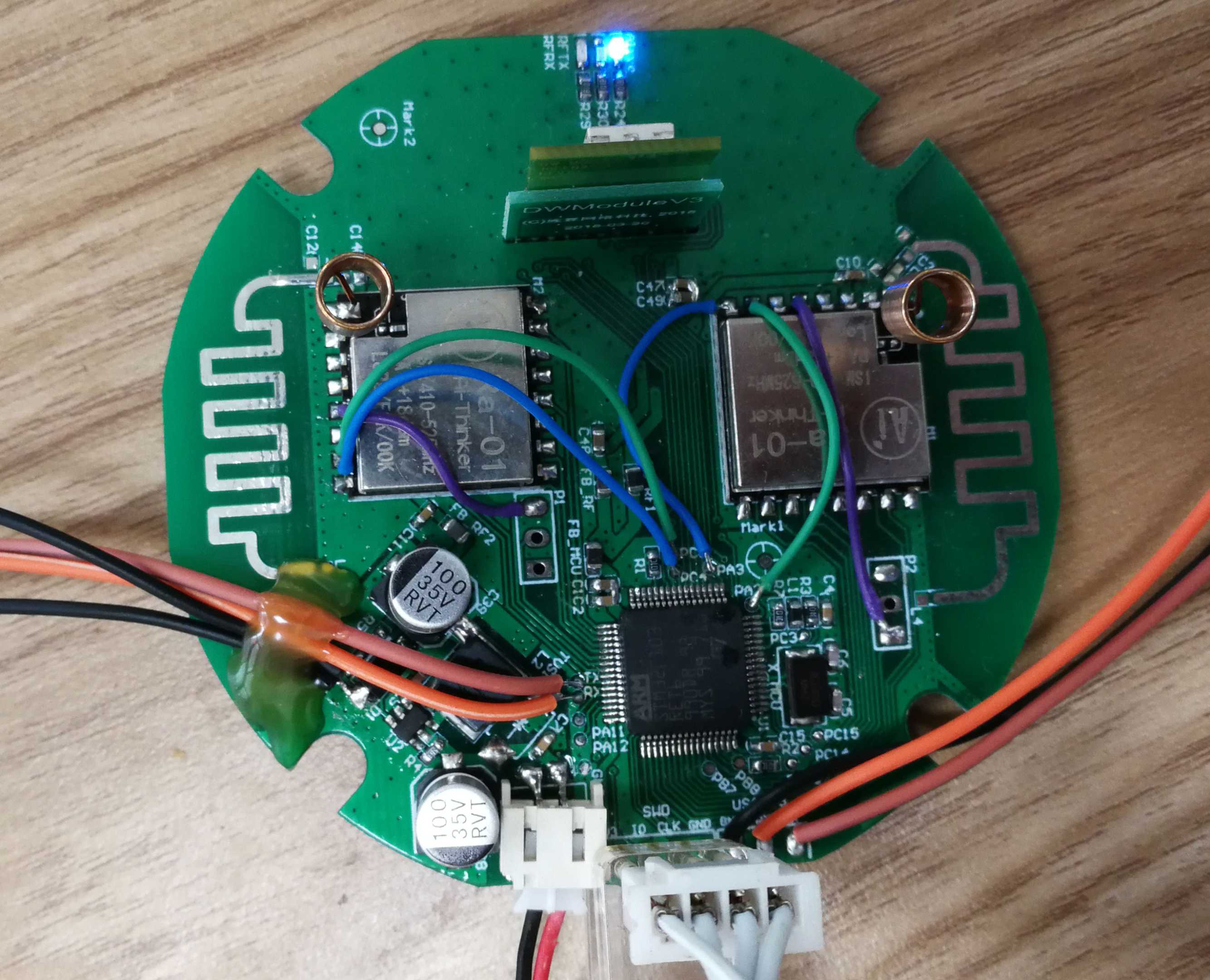
The second stage is miniaturization.
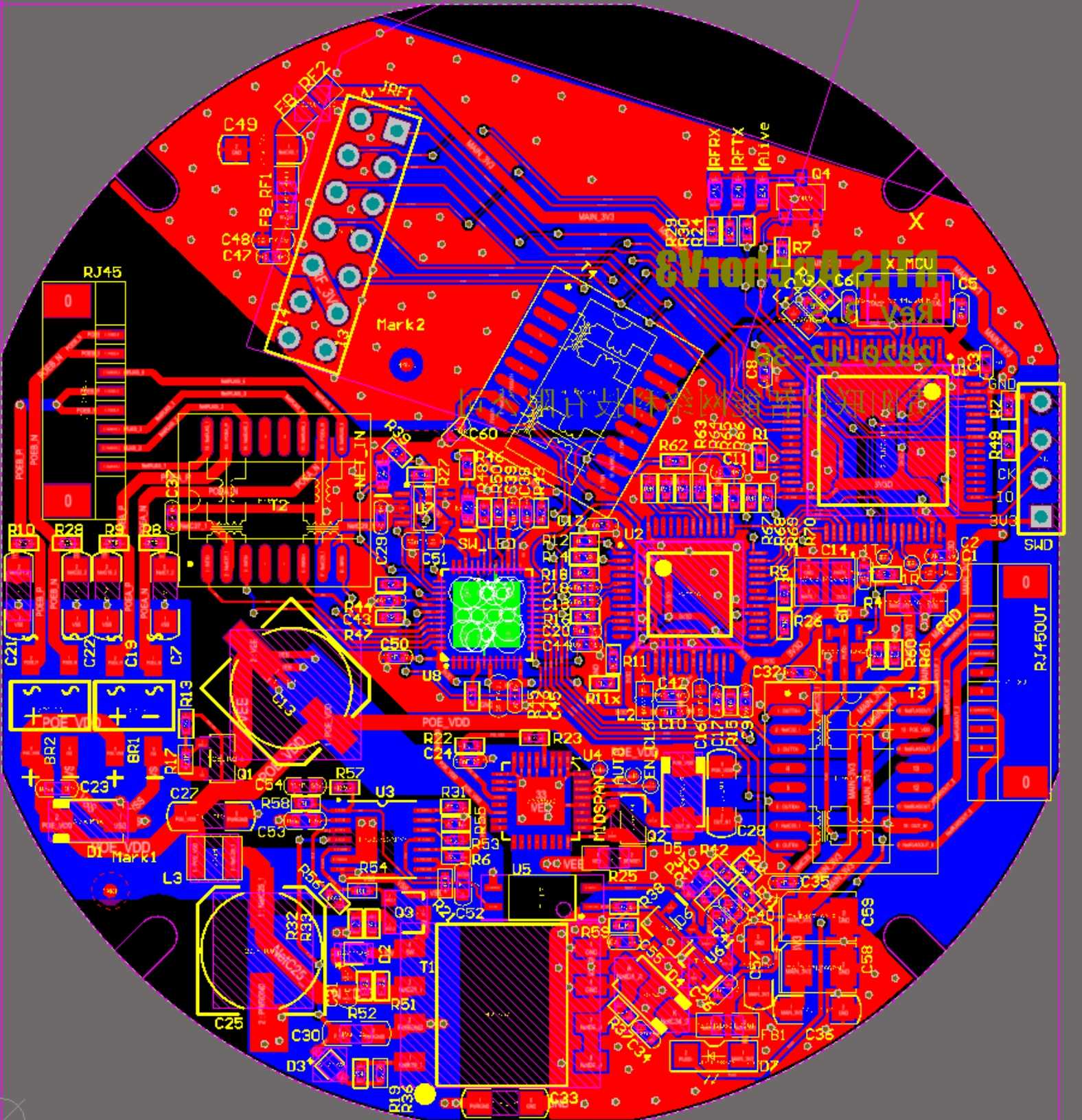
As can be seen from the above picture, ESP WIFI is no longer considered. The DW1000 module is fixed in the center of the anchor through the adapter board. On the one hand, the box space is smaller, and on the other hand, the DW1000 module is kept as far away from the PCB and the installation surface as possible to reduce interference. .
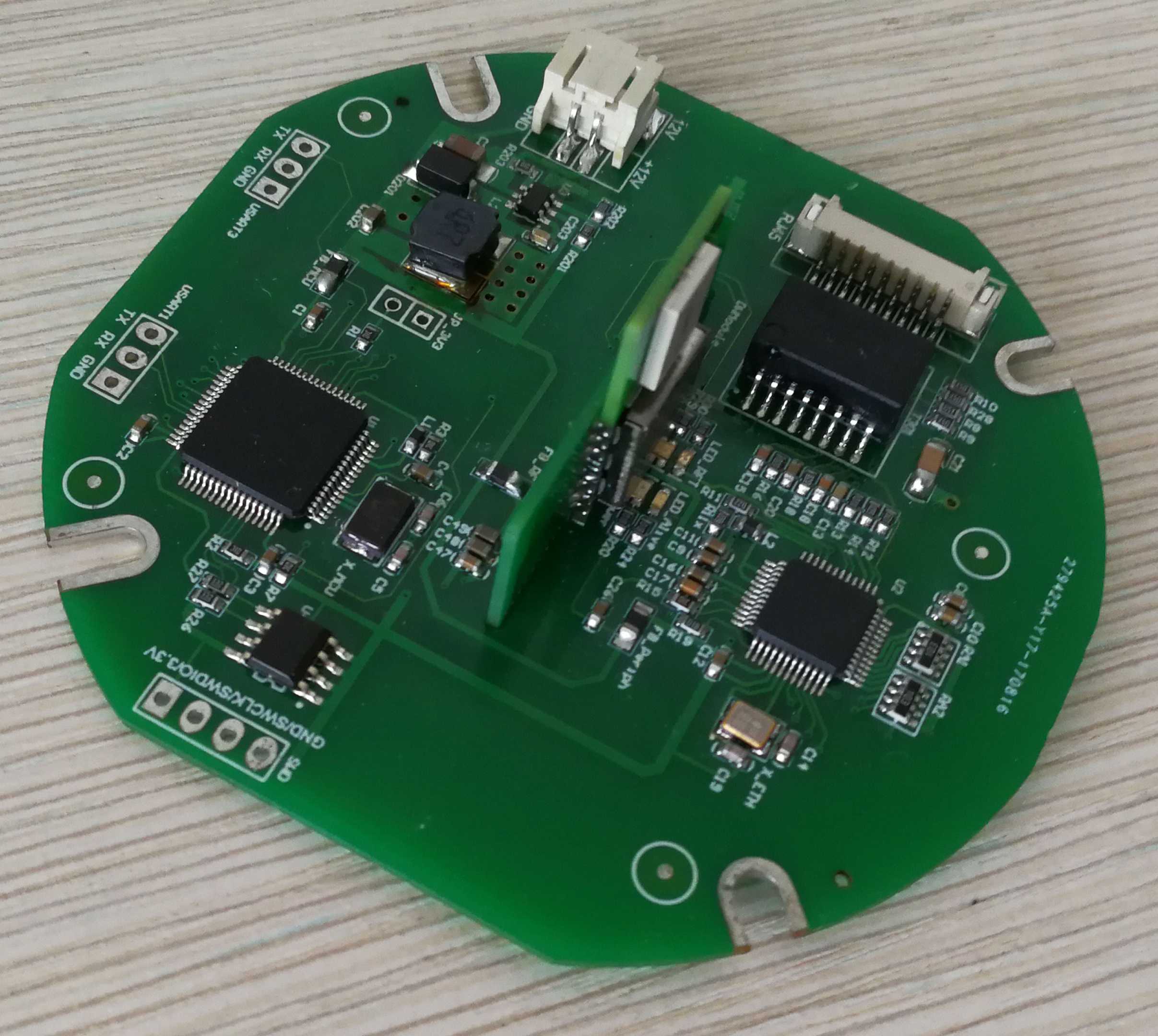
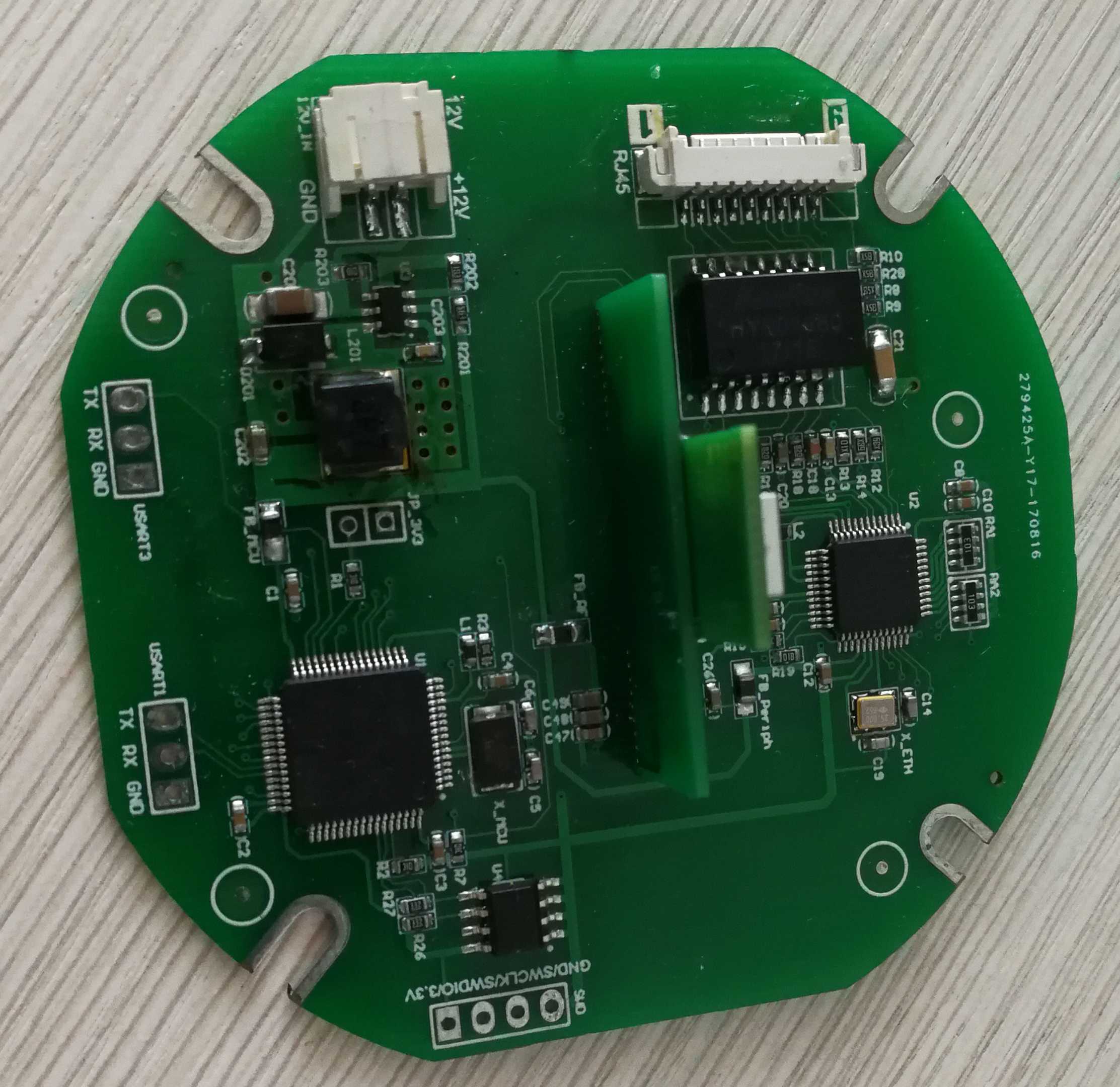
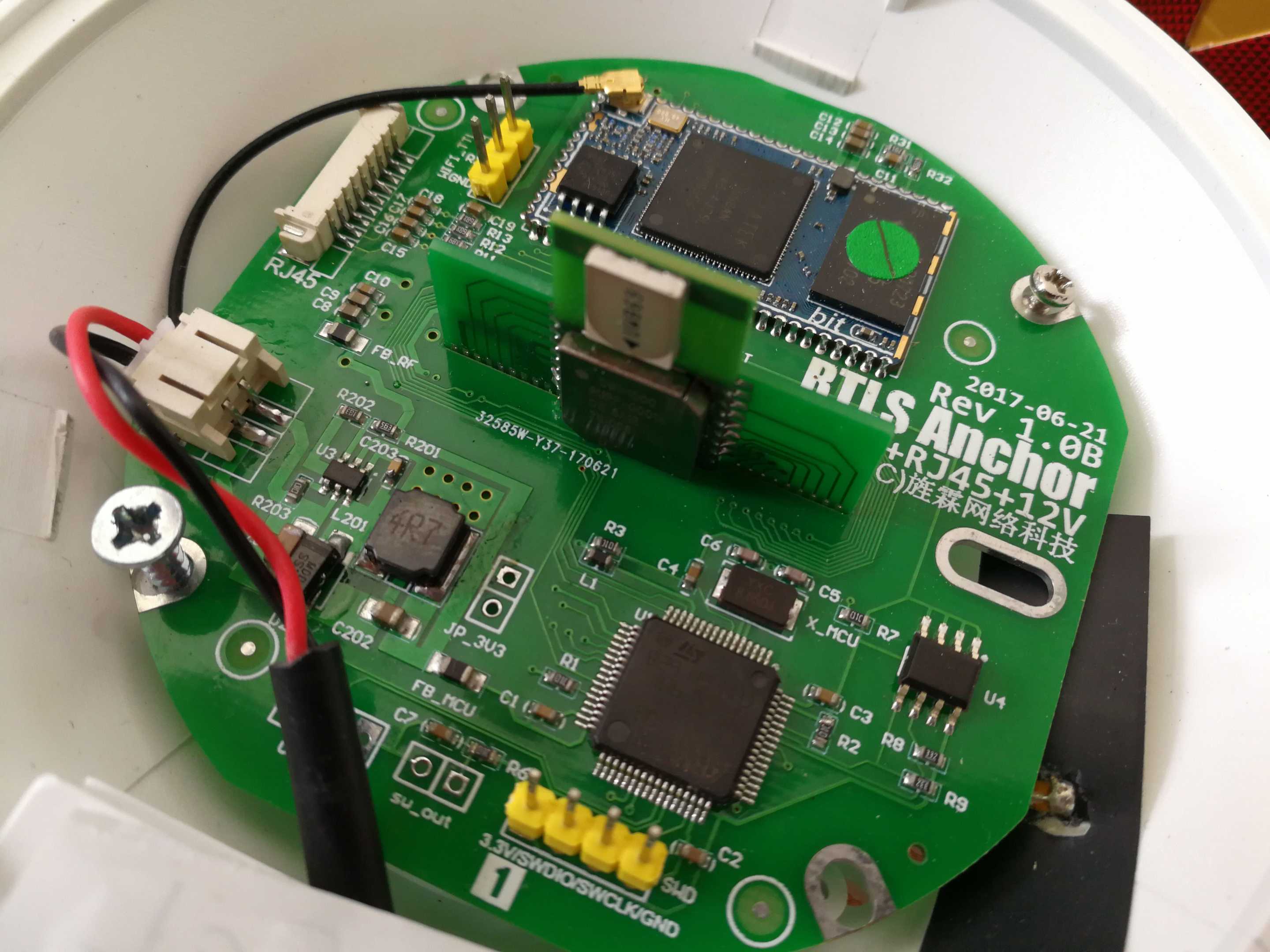
Officially as the external sales stage of the product.
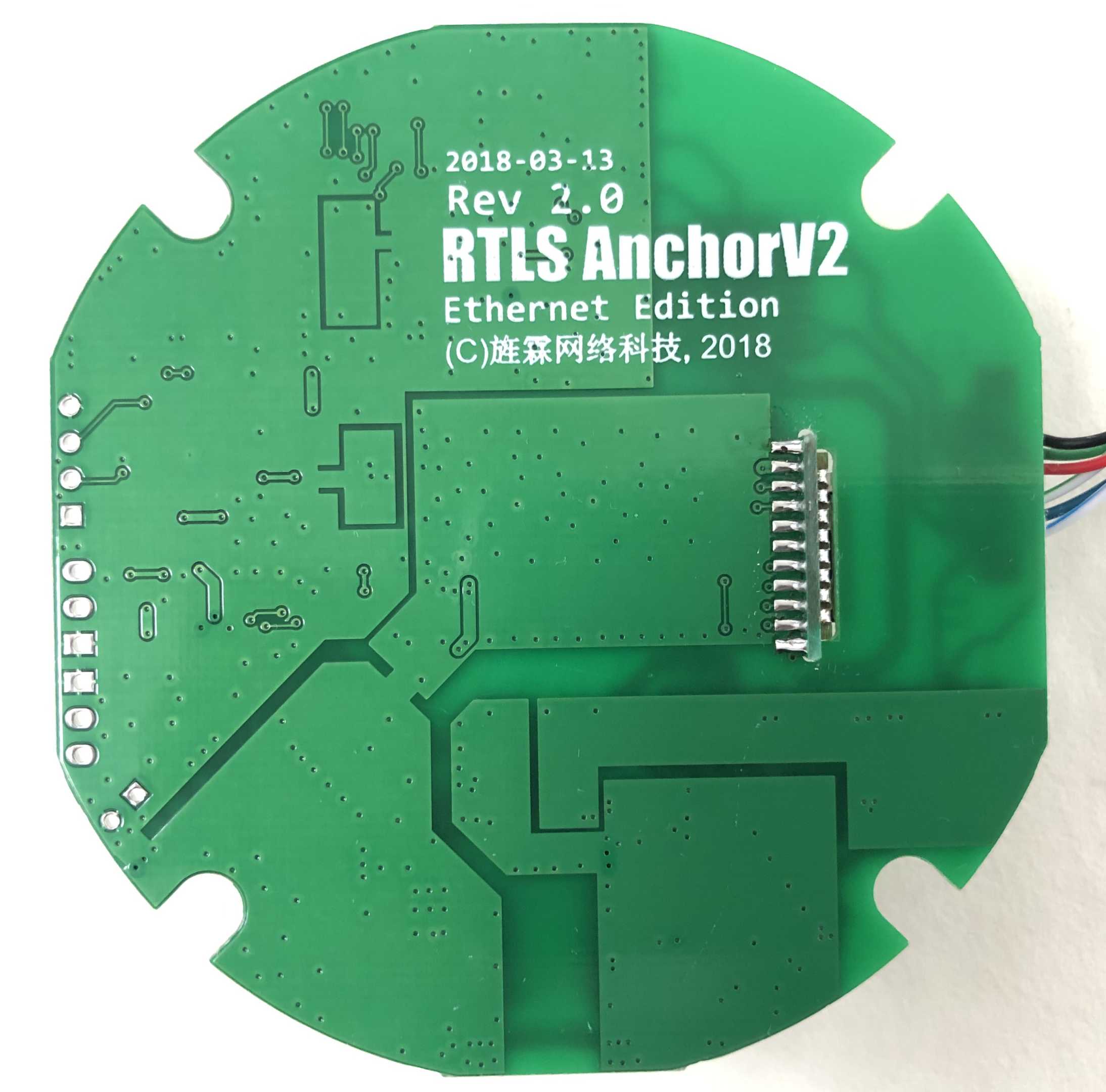
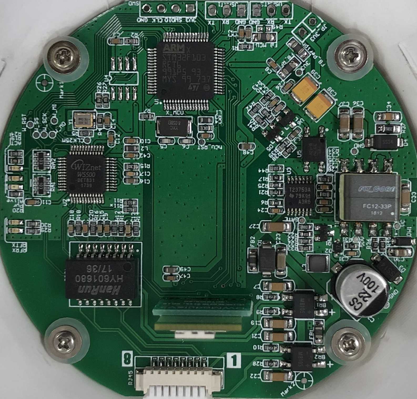
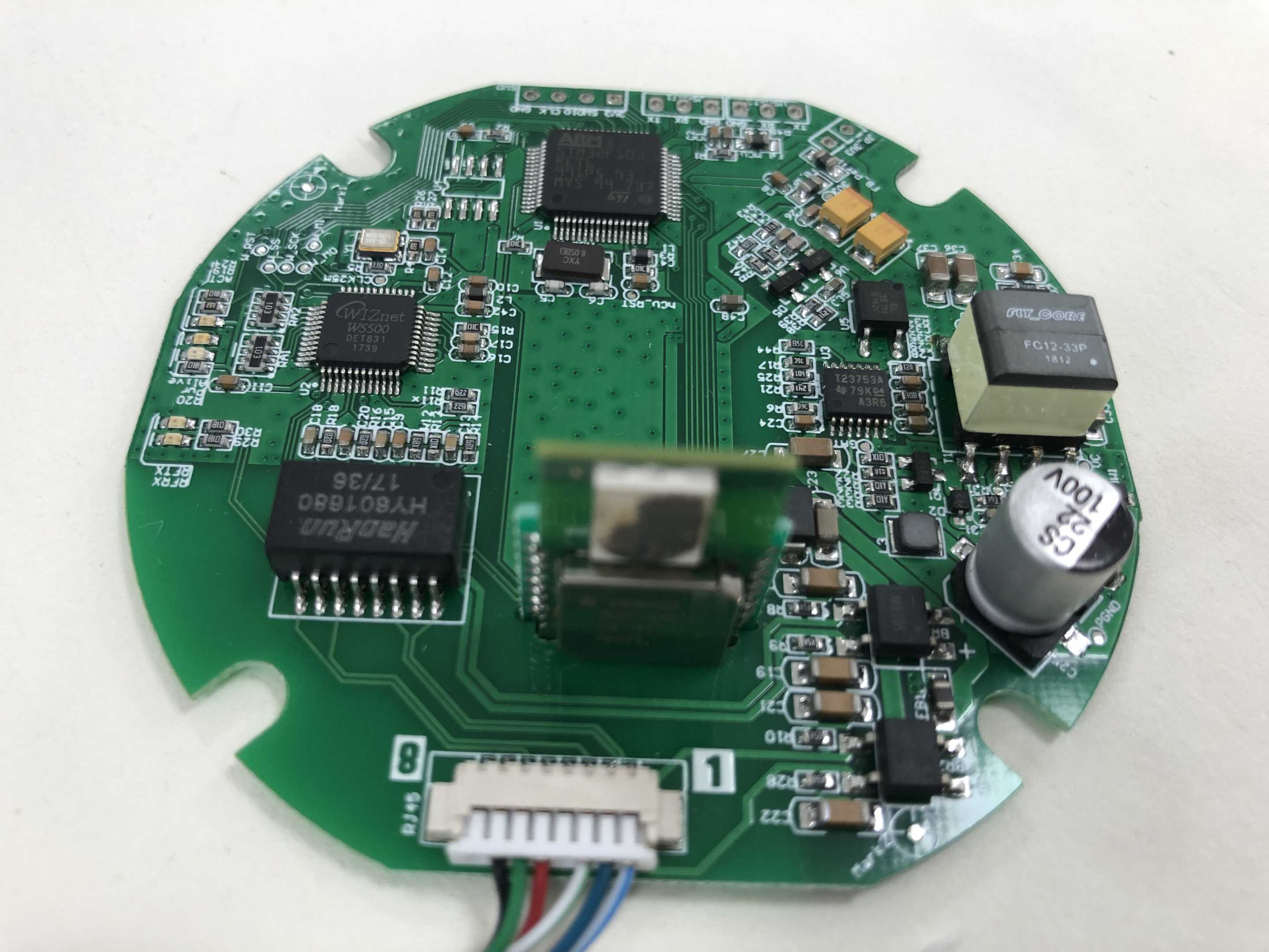
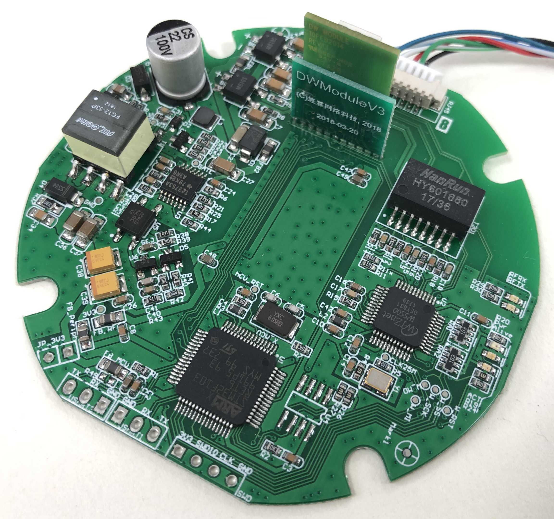
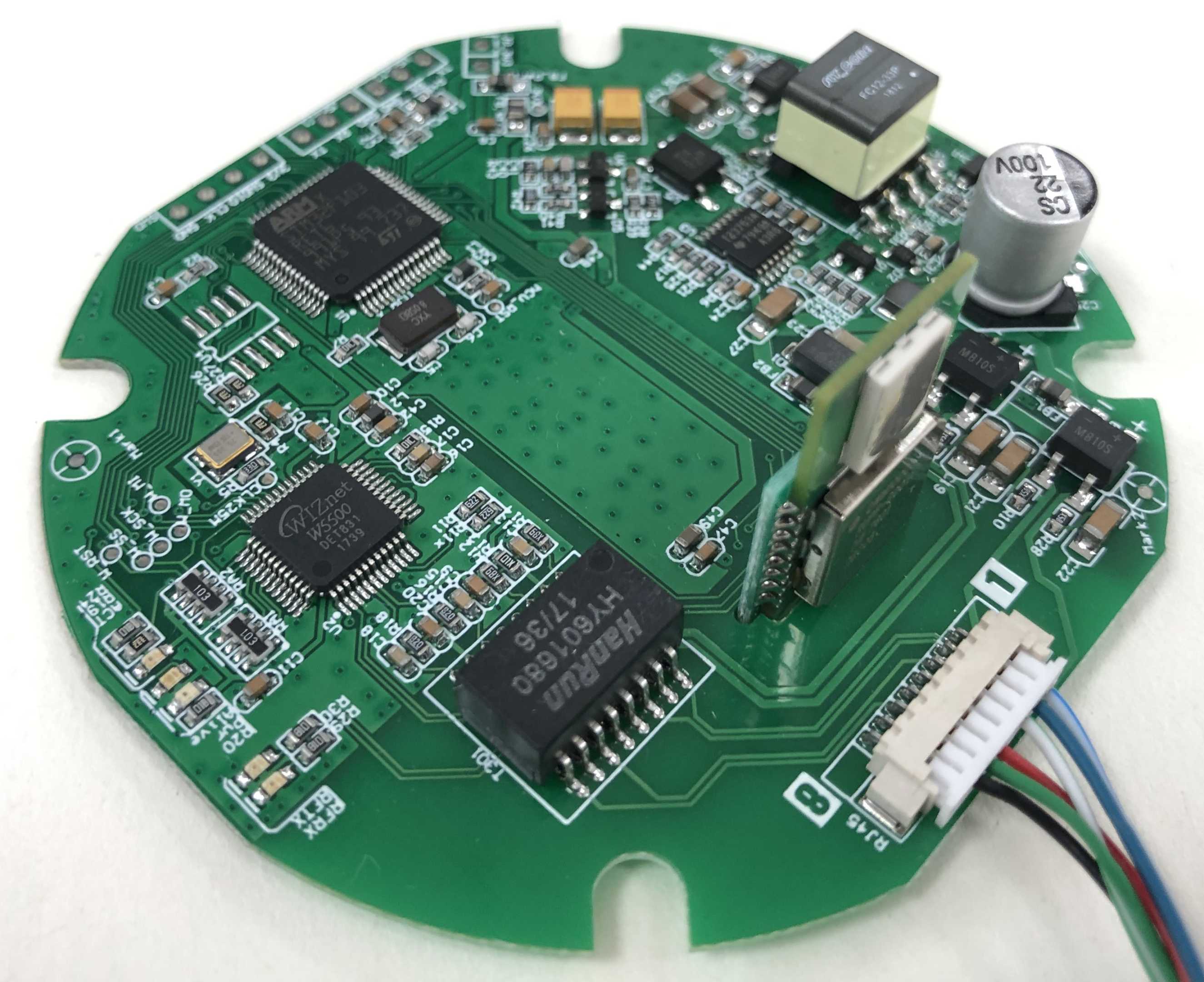
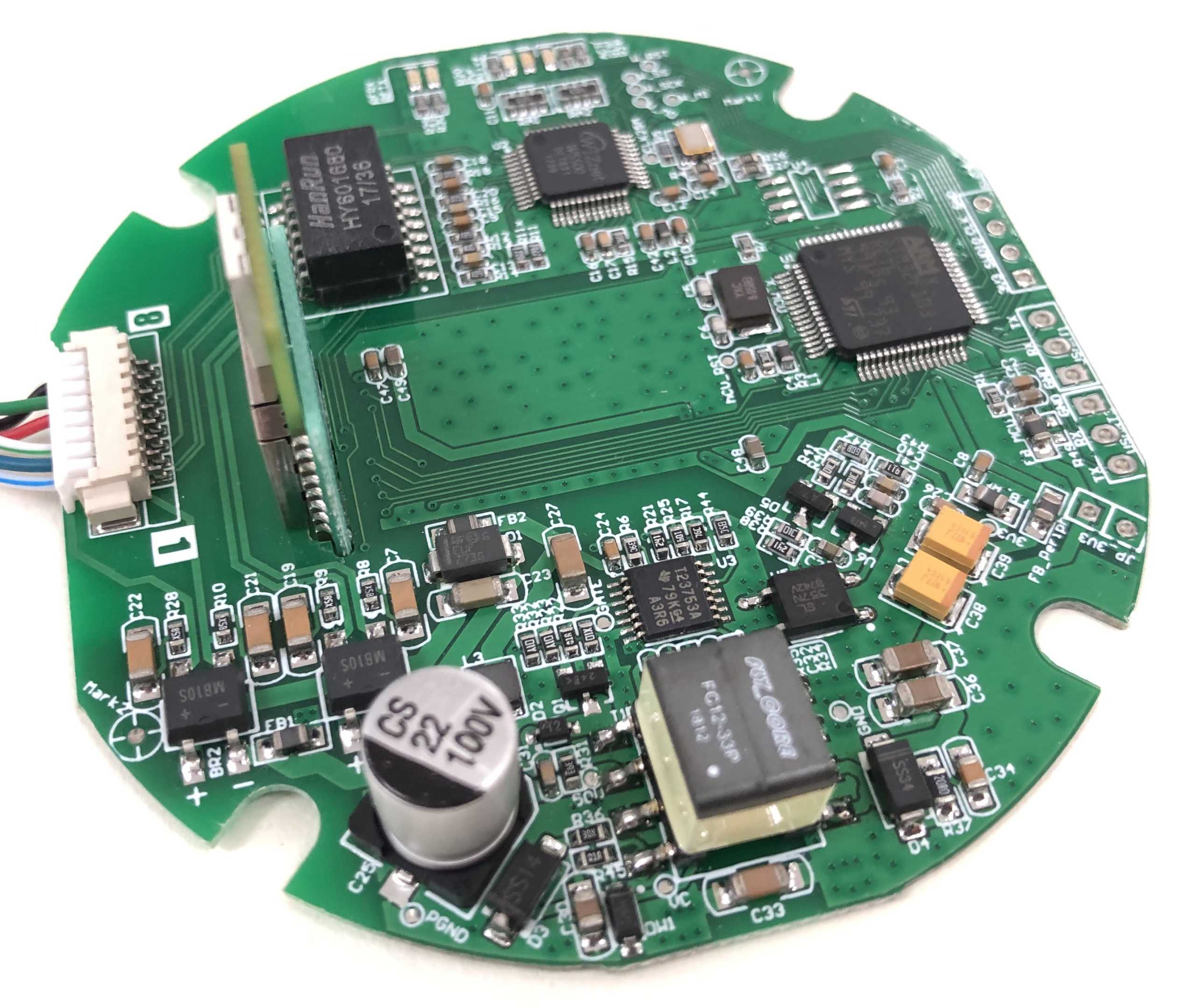
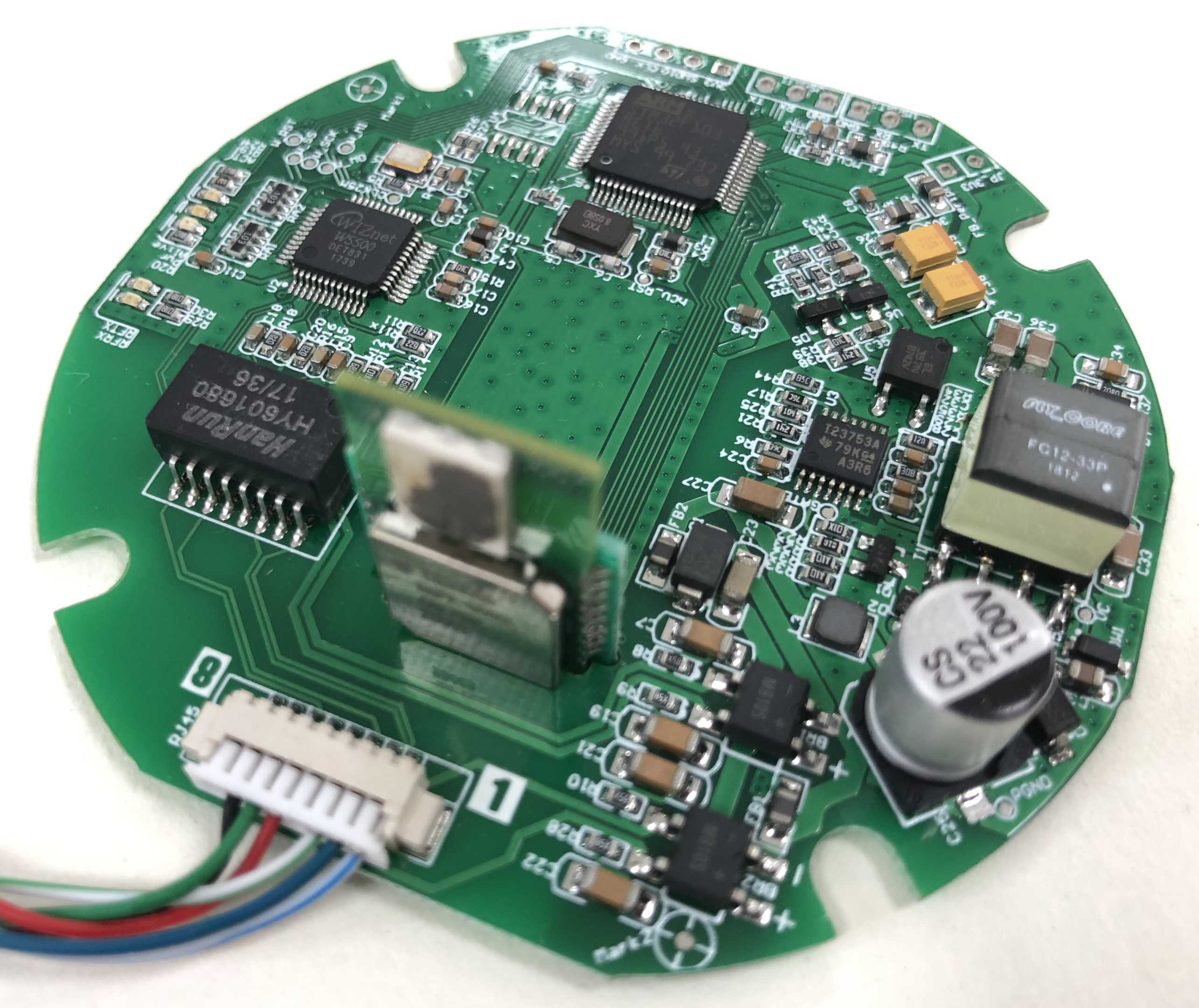

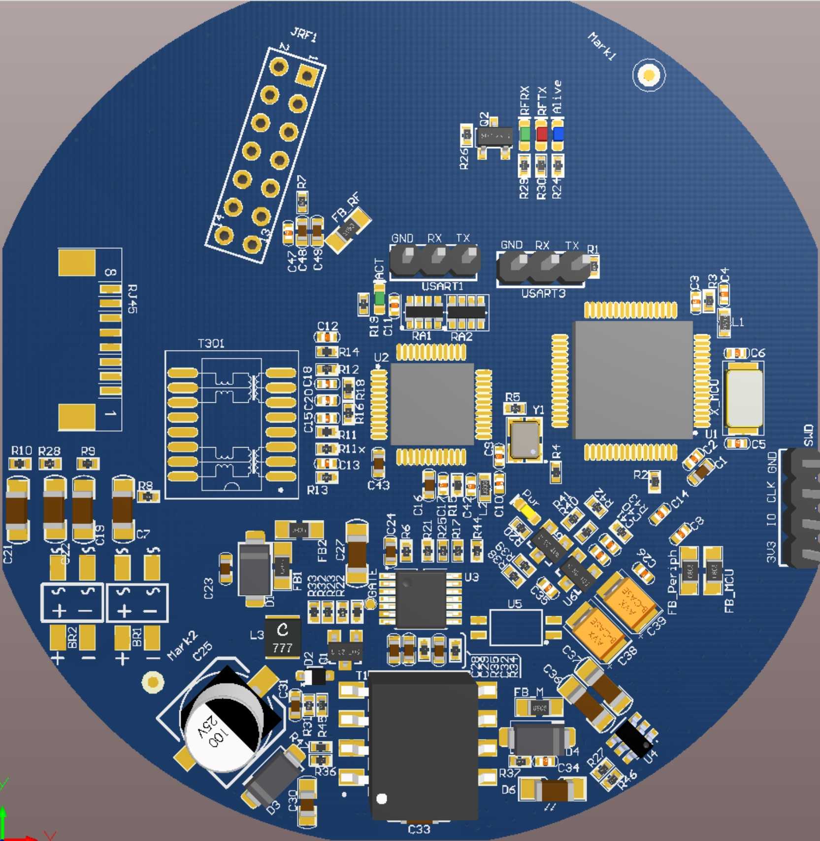
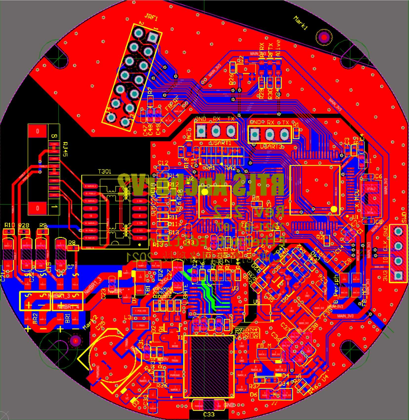
As can be seen from the above figure, the anchor at this stage uses POE for power supply. The power supply part occupies less than half of the PCB area because we use an isolated design to isolate the anchor's digital circuit from the network cable power supply to ensure the safety of the anchor's digital circuit.
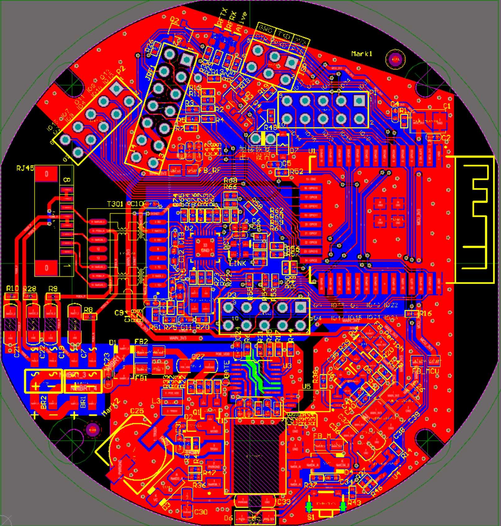
Going one step further, we integrated a network switch chip and POE power supply.
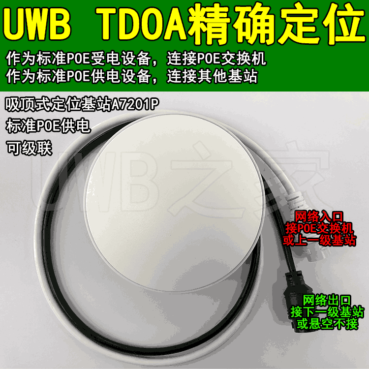
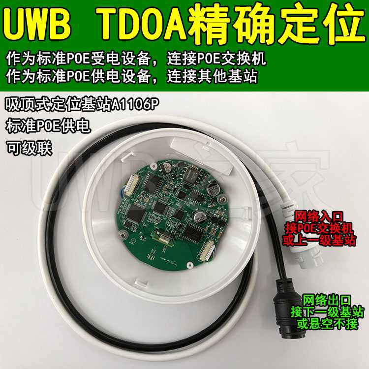
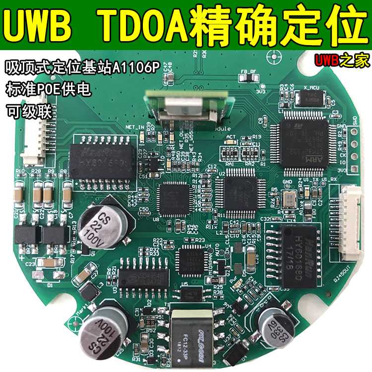
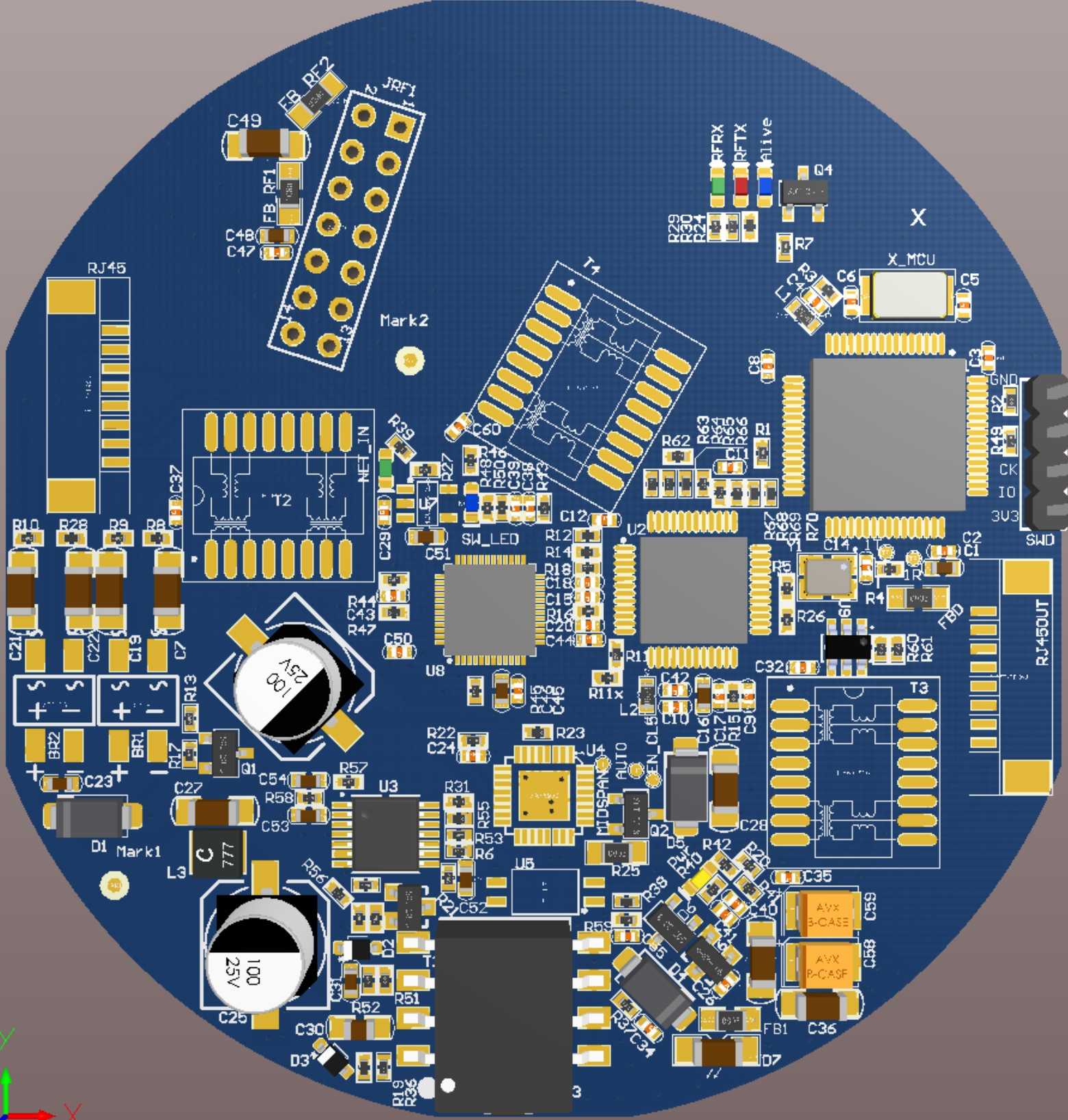
The pictures above are our original promotional photos, and the PCB is more integrated.
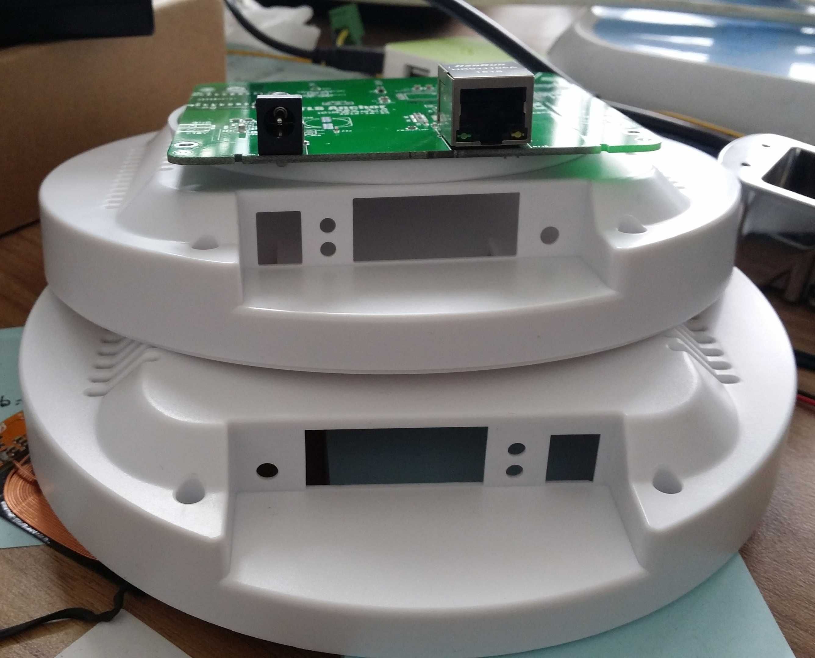
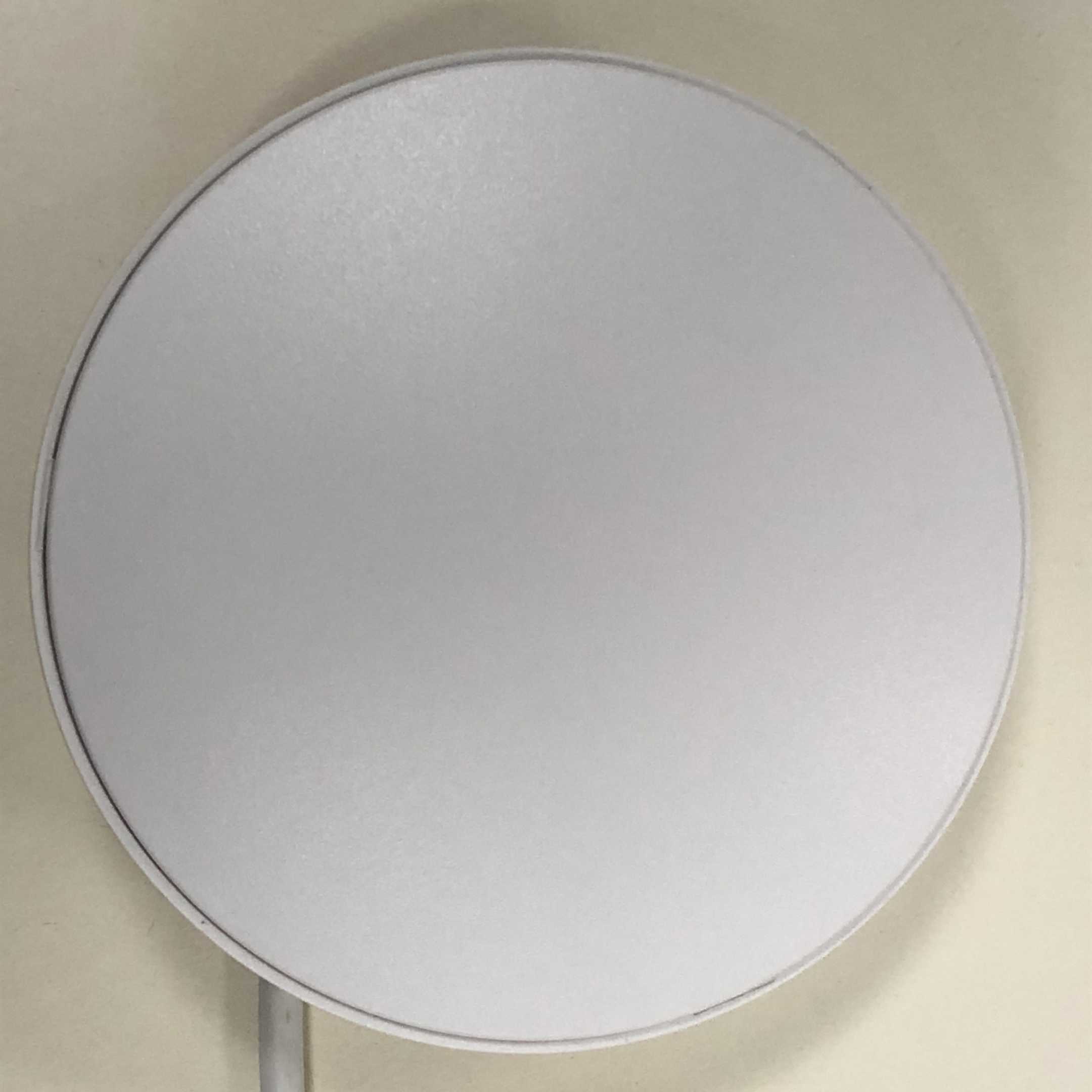
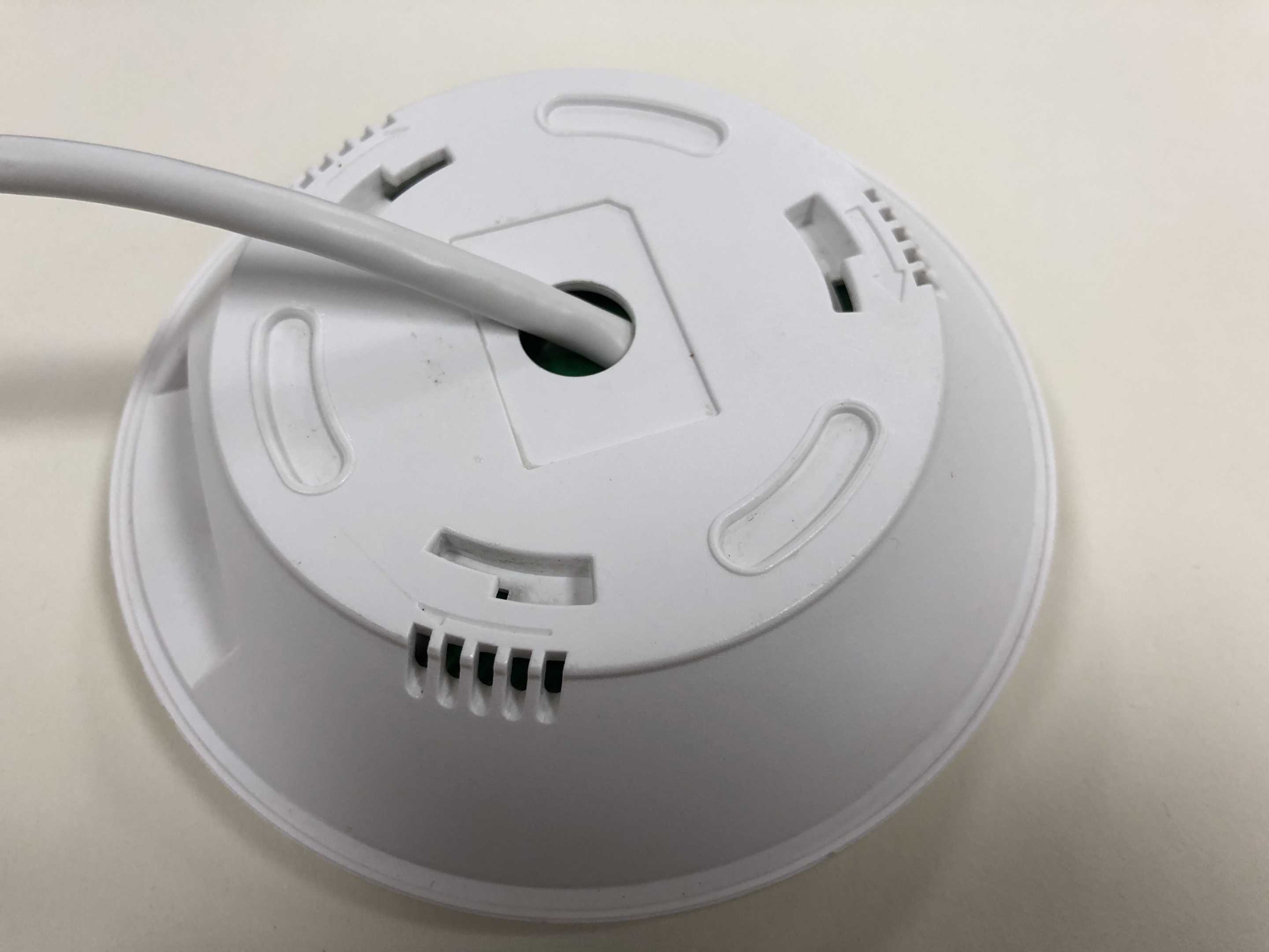
In order to facilitate disassembly and assembly, we have made some changes to the anchor.
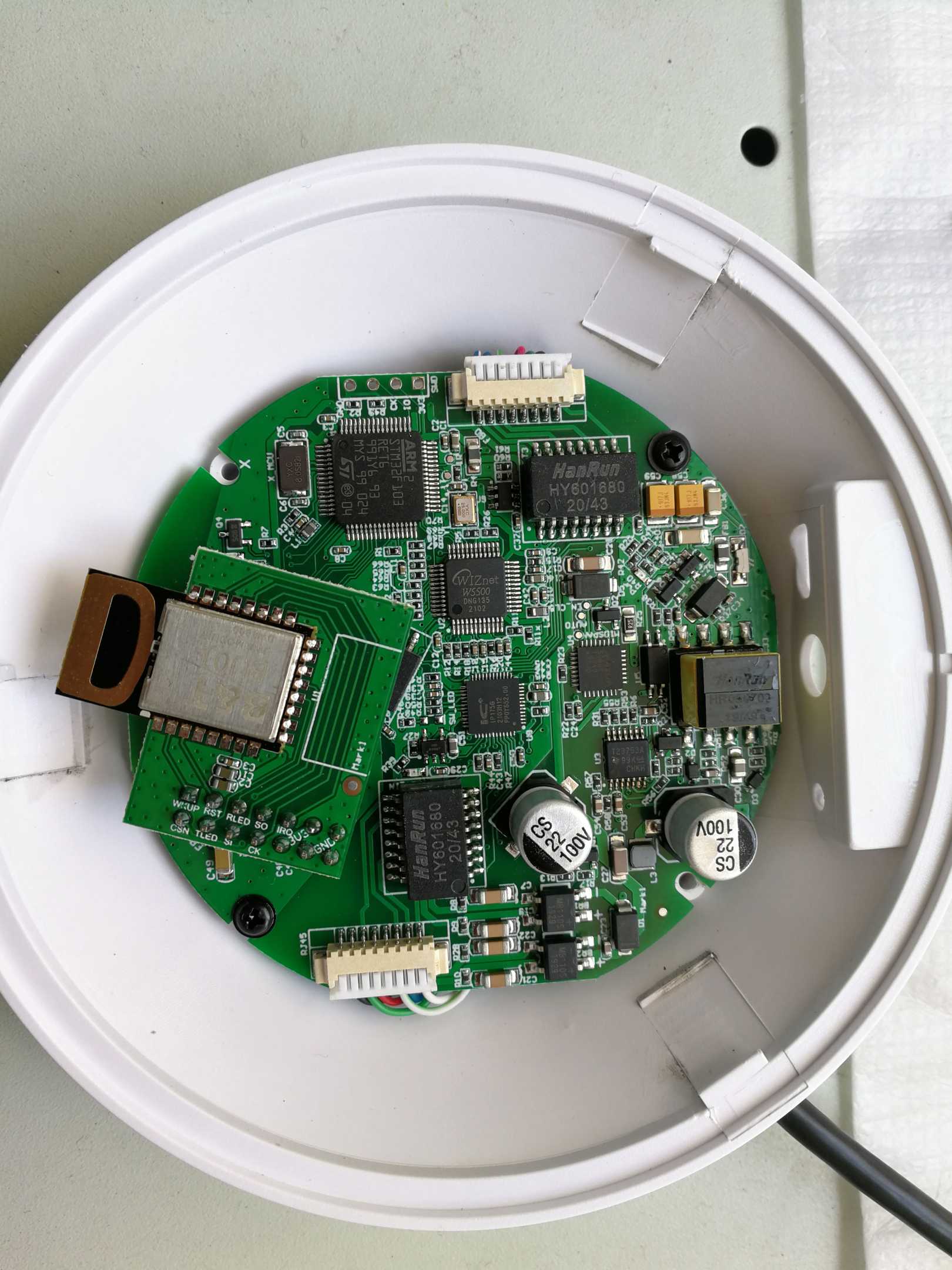
As can be seen from the above set of pictures, the structure of the anchor is more reasonable.
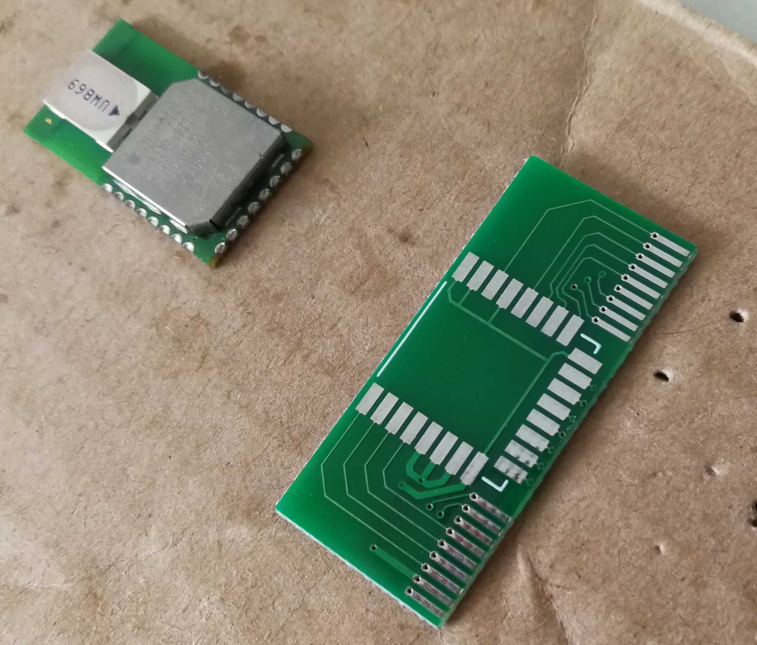
During the development process, we also tried other network connection methods.
The first picture above is using 433M radio frequency transmission, and the second picture is using MTK's WIFI module for transmission. However, both experiments were unsuccessful due to transmission speed issues.
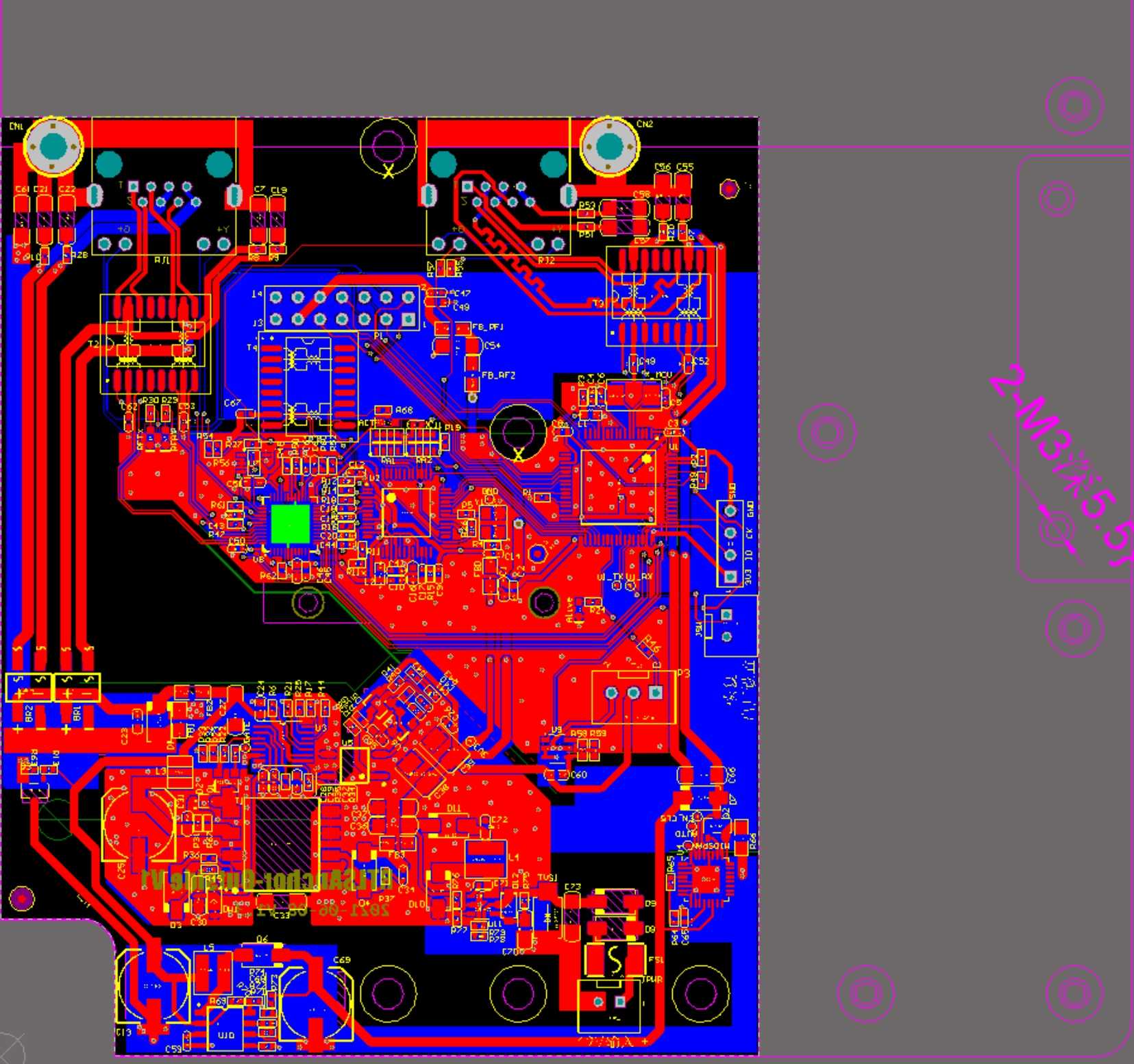
Later, we plan to use ESP32 as the WIFI interface and also use ESP32 as the main control MCU, so that STM32 and W5500 can be eliminated. On the one hand, it can save costs, on the other hand, it can support both WIFI and Ethernet. If the MCU is replaced, the anchor firmware needs to be completely rewritten, which is a bit of a workload. Not long after this plan was launched, the company decided to stop the project, and the research and development of new anchors was also suspended. The picture below is the new anchor PCB using ESP32 as the main control.
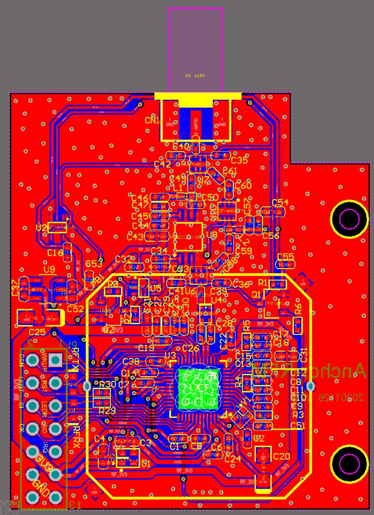
We also designed a waterproof outdoor anchor. The radio frequency signal is led out from the UWB module to the external antenna using an IPX socket. We also designed a bright LED at the bottom of the anchor as the anchor identification (the switch can be controlled by software).
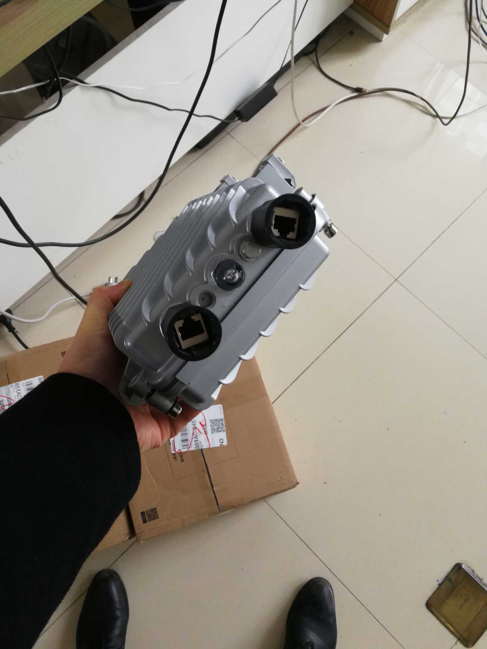
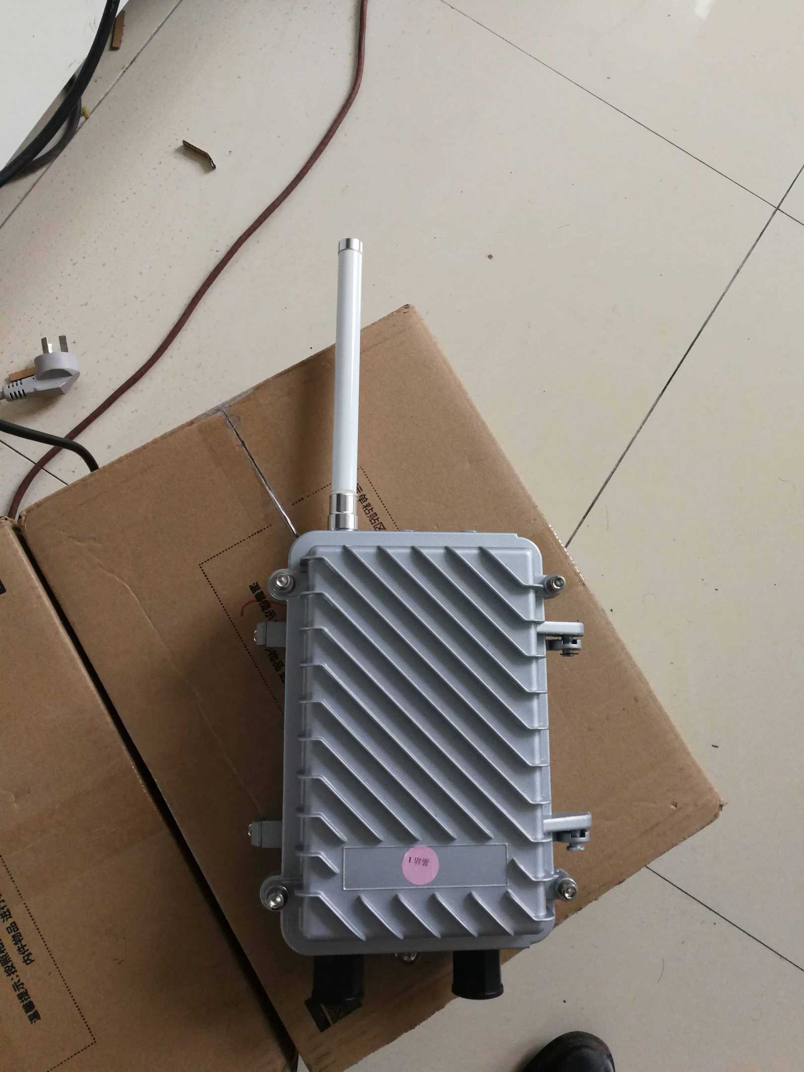
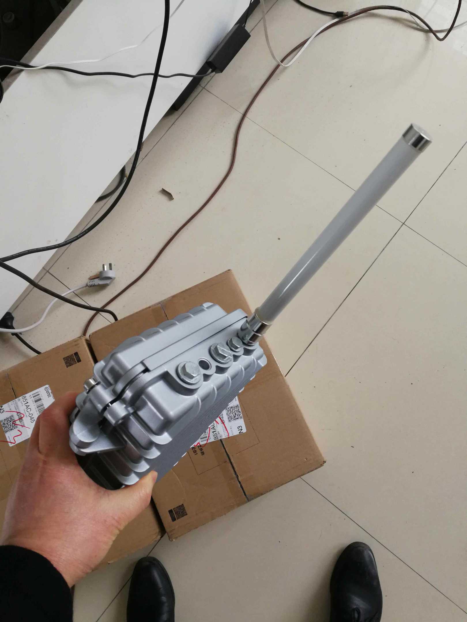
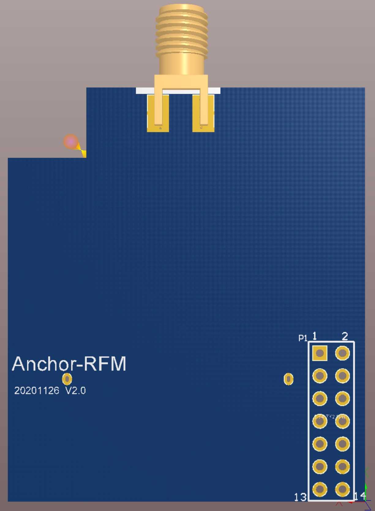
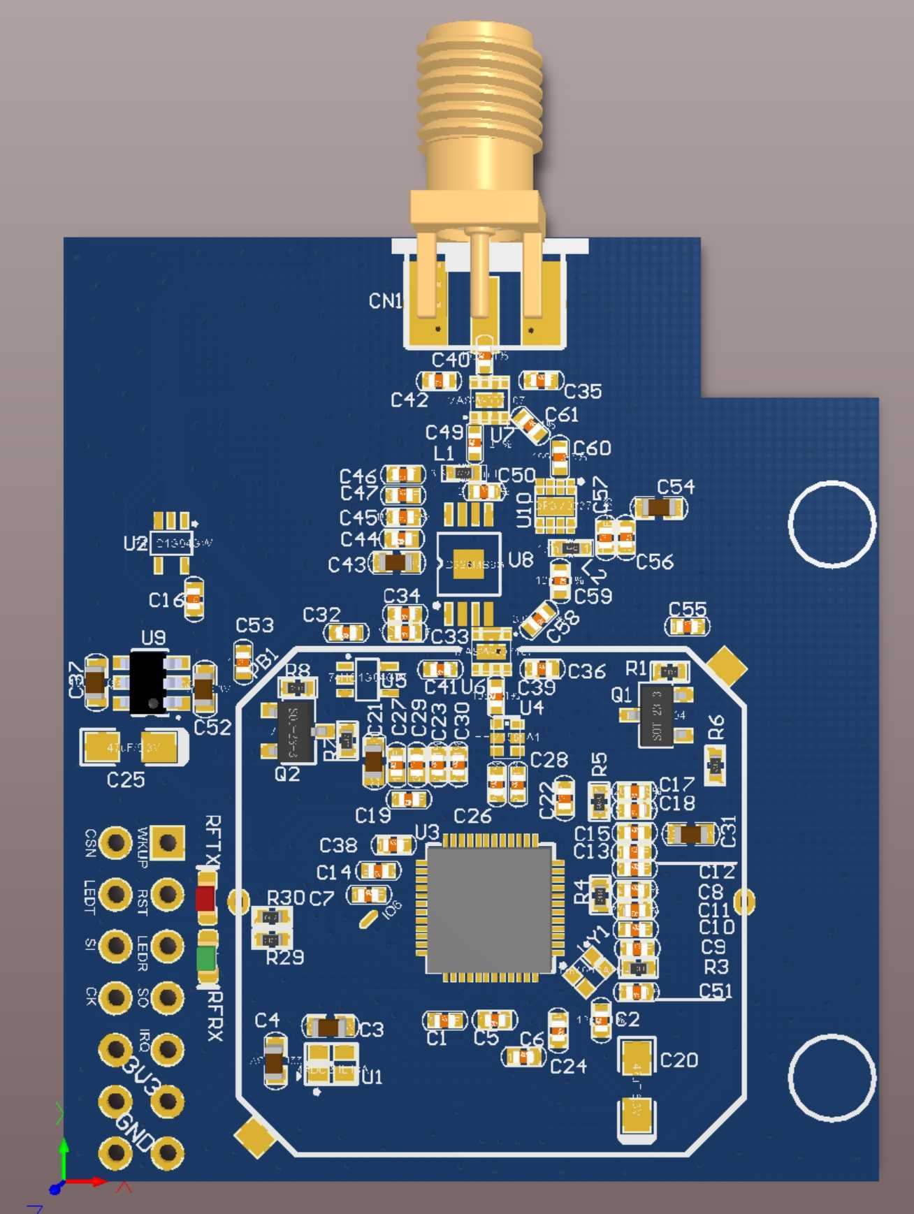
We have also designed a special UWB module for outdoor anchors, using an SMA interface to connect to peripheral antennas.