Preface
This is a series of articles that will introduce you to how to implement a UWB precise location system using TDOA technology.
IMPORTANT NOTE:
- Q: Do I need basic knowledge to create this location system?
- A: This article is not for beginners. It requires a basic knowledge of electronic technology and software programming.
- Q: Are your hardware/software open source?
- A: It is not open source.
In the article, I will introduce how to implement the UWB location system and tell you how to overcome the difficulties, but I will not directly give you the Gerber file of the PCB to make a board, nor will I give you the source code of the software, nor will I give you the compiled firmware.
I'm not going to give you any direct results, I'm just telling you how. - Q: I am personally very interested in UWB location. Can I make a location system?
- A: If you have a strong hardware/software background and a lot of time, you can certainly do it. This article is just for you to read!
- Q: I am a commercial company and I want to develop the UWB location system into a commercial product.
- A: Of course. This article is also written for you. If you want to build the entire system from zero, after reading my article, you only need to draw the circuit and make the board; conceive the software structure and then coding.
In this way, I will mention all the difficulties in the article and introduce the solutions. You don't need to hire people to do algorithm research. If you want to save trouble and time, you can directly purchase our circuit diagram (AD engineering files), purchase our software source code, and then quickly enter the production process. (Website: https://uwbhome.top )
Starting in 2016, we started the UWB location project and officially stopped this project by the end of 2021. Now with the permission of the boss, it is decrypted. So I wrote out the entire project process.
If you are interested in UWB location, after reading this series of articles, you should be able to implement a UWB location system by yourself.
If you are using it commercially, it is recommended to purchase our technology (by the way, advertising, it is definitely cheaper than doing it yourself from scratch, mainly because it saves trouble and gets quick results, so we have been through the pitfalls you may fall into.
Website: https: //uwbhome.top ).
In recent years, UWB has become very popular. It has been speculated for a long time, but it seems that it has not been widely used in daily life.
However, in some specific fields, applications are becoming more and more widespread, such as underground coal mine location/chemical production industry location, etc. These high-risk industries have seen the benefits of UWB, so they are being used more and more.
I won't write much about the wireless features of UWB, as there are already too many introductions on the Internet.
UWB Chip
Currently, the UWB chip of DecaWave Company in Ireland is widely used. I haven't paid attention to this field for a long time. I visited DecaWave's website some time ago and found that it has changed and become a department of Qorvo.
It is said that it was renamed Qorvo after being acquired by Apple.
We use the DW1000 chip, which is really powerful. Let's not talk about its UWB related technologies. In terms of low power consumption, it is really amazing. We once had a development board. When I was testing low-power consumption, I accidentally set the chip to deep sleep.
No matter what I did, I found that the chip didn't respond. I thought the chip was broken, so I left it aside. But a few weeks later, I picked up the "bad" board and tested it, and suddenly found that the chip was good again.
It turns out that because there are several small capacitors on the template, although the power is cut off, the small capacitors are still supplying power to the chip, so the chip has been sleeping.
After a few weeks, the small capacitors ran out of power, and the chip was completely out of power. Power on and reset, the chip is normal again.
The following are the technical data of DW1000:
- Supports 110 kbit/s, 850 kbit/s & 6.8 Mbit/s data rates
- 6 frequency bands supported with center frequencies from 3.5 GHz to 6.5 GHz
Transmit Power ?14 dBm or ?10 dBm
Transmit Power Density < ?41.3dBm / MHz
Preamble Length 64 μs to 4 ms
Supports Packet Sizes up to 1023 bytes
Modulation: BPM with BPSK
Integrated FEC and CRC insertion and checking
SPI interface to host controller (20 MHz max)
Allows easy integration with wide range of μControllers
Single Supply Voltage 2.8 V to 3.6 V
Low Power Consumption
Transmit mode from 31 mA*
Receive mode from 64 mA*
2 μA watchdog timer mode
100 nA deep sleep mode
Media Access Techniques
FDMA: 6 channels
CDMA: 12 different channel codes
Supports both two way ranging and one way ranging, using Time of Flight (TOF) and time difference of arrival (TDOA) methods
Fabricated in 90 nm CMOS
Industrial temperature range -40°C to +85°C
6 mm x 6 mm 48 pin QFN package
Hardware & software applications support material available from DecaWave
DecaWave provides a lot of routines for DW1000, how to send UWB data packets, how to receive UWB data packets, and several TOF ranging codes. The development board trek1000 kit provided by DecaWave also provides the source code of a TOF location sample system.
Many stores selling DW1000 development boards on Taobao claim to provide source code, and they should provide these codes.
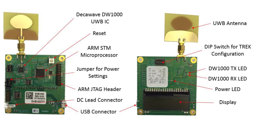
Official development board TREK1000 kit, with 4 boards
Technical difficulty one: TDOA technology
What is TDOA? The full English name of TDOA is Time Difference of Arrival. In fact, the GPS/Beidou navigation we often use, and the location technology used by mobile phones (receiving terminals) is TDOA.
The GPS chip on the mobile phone calculates the location of the mobile phone based on the time difference of the received satellite signals. GPS/Beidou uses downlink TDOA location , which means that the terminal being positioned calculates its own coordinates.
We use uplink TDOA location.
What we have to do is different. The person or object being located carries a tag, and this tag continuously sends UWB signals. We will deploy some anchors (Anchors) in the location area, and these anchors will receive UWB signals sent by Tags.
We will have a computer running a software called a location engine (RTLE). The Anchor converts the received UWB signal into some network data and sends it to the location engine. The location engine calculates the coordinates of the tag based on these data packets.
There are also companies in the industry that are doing UWB downlink TDOA location. If downlink TDOA is performed, the terminal is required to have relatively strong computing capabilities, which is also a test for the terminal's power consumption.
GPS systems have been released for so many years. They used to be very large. However, these systems have been used in more and more applications and have gradually become smaller. If you do UWB downlink TDOA location, there will be many difficulties.
Regarding the mathematical principles of TDOA technology, there is already a lot of information on the Internet, so I will briefly mention it here.
Assume that the UWB signal sent by a Tag is received by two Anchors. The two Anchors receive it at different times, and there is a time difference. UWB signals are radio waves, and the time they fly in the air is about the same as the speed of light.
This time difference can be converted into a distance difference, which is the difference between the distance between the Tag and the two Anchors. Based on this distance difference, we can draw a curve around the two Anchors.
The distance difference between all points on this curve and the two Anchors is equal to the aforementioned distance difference. This is half of the hyperbola.
If there are 3 Anchors, the signal sent by Tag can get 3 time differences. Draw three curves. The intersection of these three curves is the coordinates of Tag. What the location engine has to do is to list a few equations, then solve the equations and get the coordinates.
It's really simple in principle. The trouble lies in solving the equations. Because there will be factors such as interference/error during implementation, the intersection points of the three curves do not coincide.
What we need is to quickly calculate an approximation, as close as possible to the numerical intersection of the curves.
When we first started working, we searched online and found many papers. The author of almost every paper will say how awesome my algorithm is, cite a lot of data to prove it, and write a bunch of mathematical formulas that people can't understand.
I will discuss TDOA technology in detail later when I introduce how to write a location engine.
Technical difficulty two: clock synchronization
Since time difference is used for location, each anchor must have the same time. If you have watched war movies, you should still have images. After the commander arranges the tasks of each unit, he will say, "We will launch the battle on time at 12 o'clock.
Let's check the watch." Yes, if everyone's watches are inconsistent, some watches have already passed 12 o'clock, and some watches have not yet reached 12 o'clock, it will be a mess.
The time of each anchor is unified.
When receiving the UWB signal from the tag, the anchor will record the time it was received, and then each anchor will send this time to the location engine, and the location engine will calculate the coordinates based on the difference in these times.
When we were doing technical research, we contacted Decawave. They had a wireless clock synchronization solution that cost more than 100,000 US dollars. It was not code, just a solution.
Later, we came up with a solution and found that the wireless clock synchronization solution is actually very simple, it just depends on whether you can think of it.
These two technical difficulties: TDOA algorithm and clock synchronization scheme were indeed difficult in 2016/2017. I guess there are many companies that want to do UWB location, but after research, they are blocked by these two obstacles.
As long as you are willing to study hard, these problems will always be solved. So now there are more and more companies doing UWB location.
After you read this series of articles of mine, you will find that these two "difficulties" are actually not that difficult.
What is Our Goal
What do you get after all the fuss? In other words, what are we going to do?
To put it simply, we are building a UWB precise location system using TDOA technology.
The person or object being located carries a tag, which continuously sends UWB signals. We will deploy some anchors (Anchors) in the location area, and these anchors will receive UWB signals sent by Tags.
We will have a computer running a software called a location engine (RTLE). The Anchor converts the received UWB signal into some network data and sends it to the location engine. The location engine calculates the coordinates of the tag based on these data packets.
This process is the standard TDOA location process, which is very simple.
In this process, there are two types of hardware involved: tags and anchors; the software involved are: tag firmware, anchor firmware, and location engines.
Of course, the above is a simplified version. Commercial products should also have some other software:
- Tag configurator
- Anchor configuration program
- Location engine manager
For example, if we need to change the channel for UWB communication, do we need to recompile the tag firmware and anchor hardware and then flash them to the board? Wouldn't it be more convenient if you use a configuration program to set the channel parameters?
Also, we want to add a new function to the firmware. Do we need to remove the board, connect the JTag and re-flash the firmware? Wouldn't it be more convenient to upgrade the firmware directly over the Internet?
The location process is also more complicated in real environments. Usually, the maximum communication range of UWB chip DW1000 is 200 meters to 300 meters. What if the area we want to target is large? Generally, multiple small areas are divided into one large area.
Therefore, the location engine must support multi-region location.
Hardware Design and Selection
In terms of hardware, what we need to do is two things: tags and anchors.
The most important components in hardware selection are the two components: UWB chip and MCU.
We use DW1000 for UWB chip. Anyone who plays electronics knows that the design of radio frequency circuits has always been difficult. Therefore, analog electrical engineers are more valuable than digital electrical engineers, and the older they are, the more valuable they are.
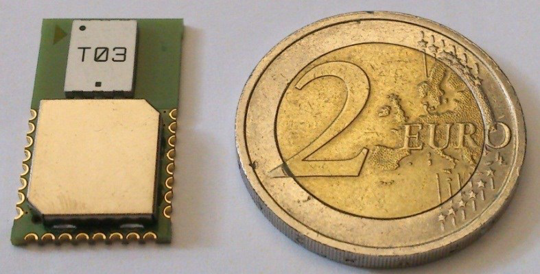
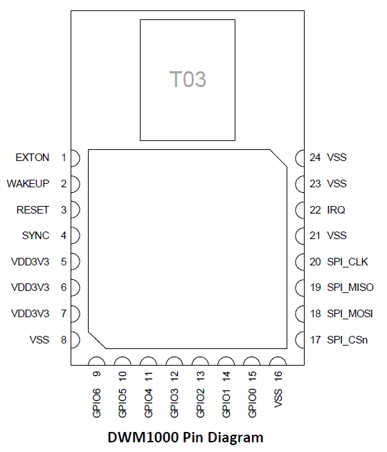
Therefore, we do not use the DW1000 chip directly, but use the module DWM1000. The original factory packages the DW1000 into a module, so we don't have to worry about the radio frequency part. The module has a set of SPI interfaces, and we can happily connect it to the GPIO of the MCU.
MCU selection. The main control MCU we use is the STM32F103 series. This series of chips was very popular a few years ago. If I were to choose now, I would definitely choose ESP32. ESP32 is cheap, has good performance, and is highly scalable. Around 2020, we suffered from the price increase of ST's chips.
The normal price of the STM32F103RET6 we use for location anchors is only about 14 yuan, and the highest price rises to about 500 yuan, which is higher than the shipping price of our anchors. It's crazy.
Because STM32F103 was used before, the introduction of this article also uses it as an example. If you use ESP32, there is still a lot of detailed work to be done. For example, ESP32 has WIFI and Bluetooth, which involves how to configure the network.
ESP32 can also add an additional chip to create a wired Ethernet connection, which involves wired and wireless dual connections. There will be two IP addresses in the network, and there are many details to consider.
So let's not consider the ESP32 for now, and let's just use the STM32F103.
Whether it is a anchor or a tag, because the DWM1000 module is used, the hardware design is mainly the digital circuit part, which is a typical circuit, and there is basically no difficulty.
Anchor Hardware Design
The anchor will have more functions and has higher requirements for RAM and Flash, so the MCU chooses STM32F103RET6.
In addition, you need to connect to the network. The network interface chip uses W5500. This chip also uses the SPI interface to connect to the MCU. I have used the W5500 in several projects before and am familiar with it, so I chose it.
Of course, if you choose other familiar network interface chips, that's no problem.
For the power supply part, if you are doing experiments by yourself, you can directly use DC12V or DC5V. We use POE power supply in our products. The POE power receiving chip uses TI's TPS23753A, and uses an isolated design to protect the anchor circuit.
In fact, our initial version used DC 12V power supply, and I have always wanted to use POE power supply. I drew several versions of the circuit and made several samples, but I still couldn't get the POE right.
Later, our team expanded and added a guy who specialized in hardware, and he finally solved POE.
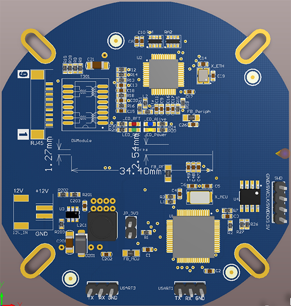
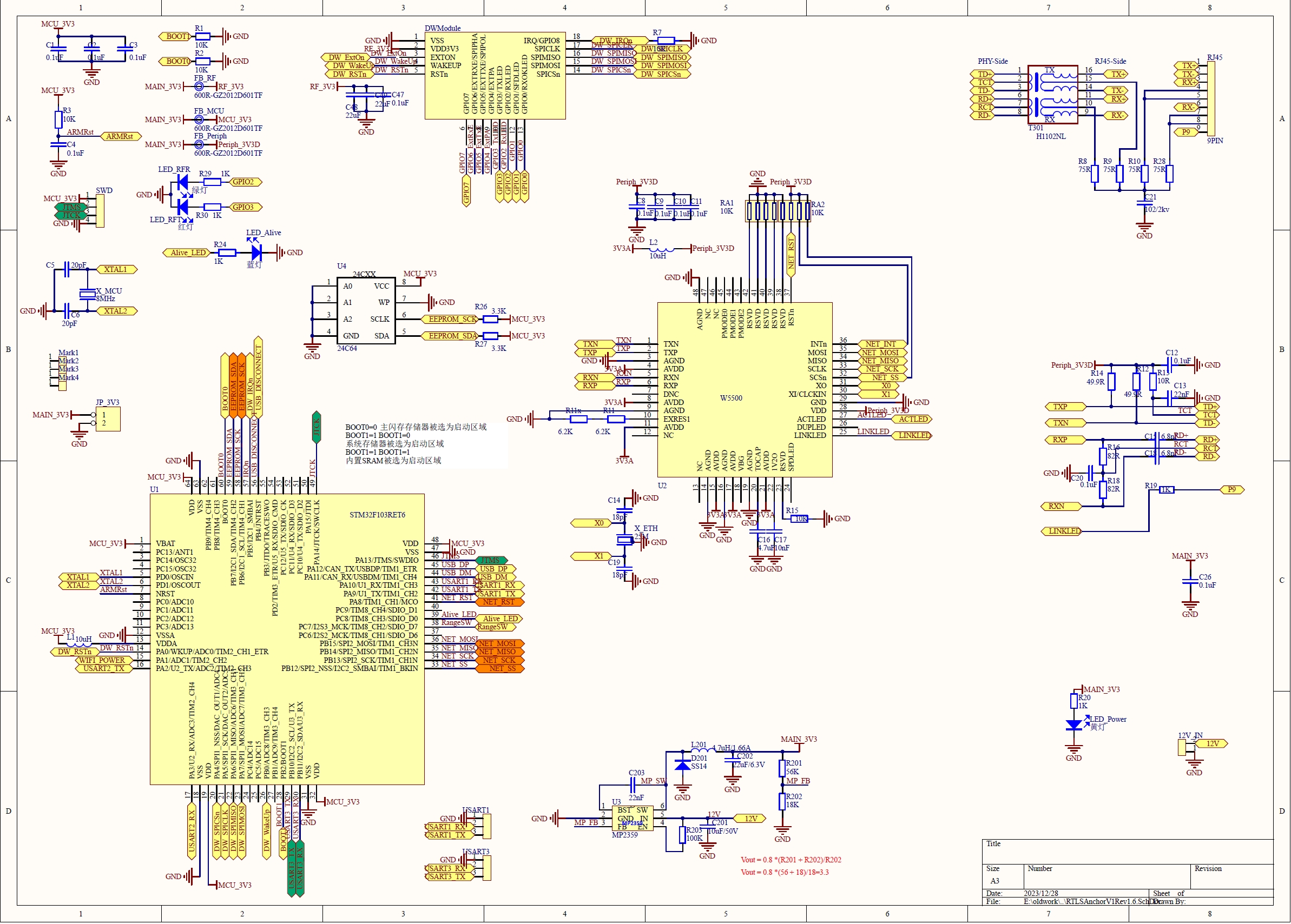
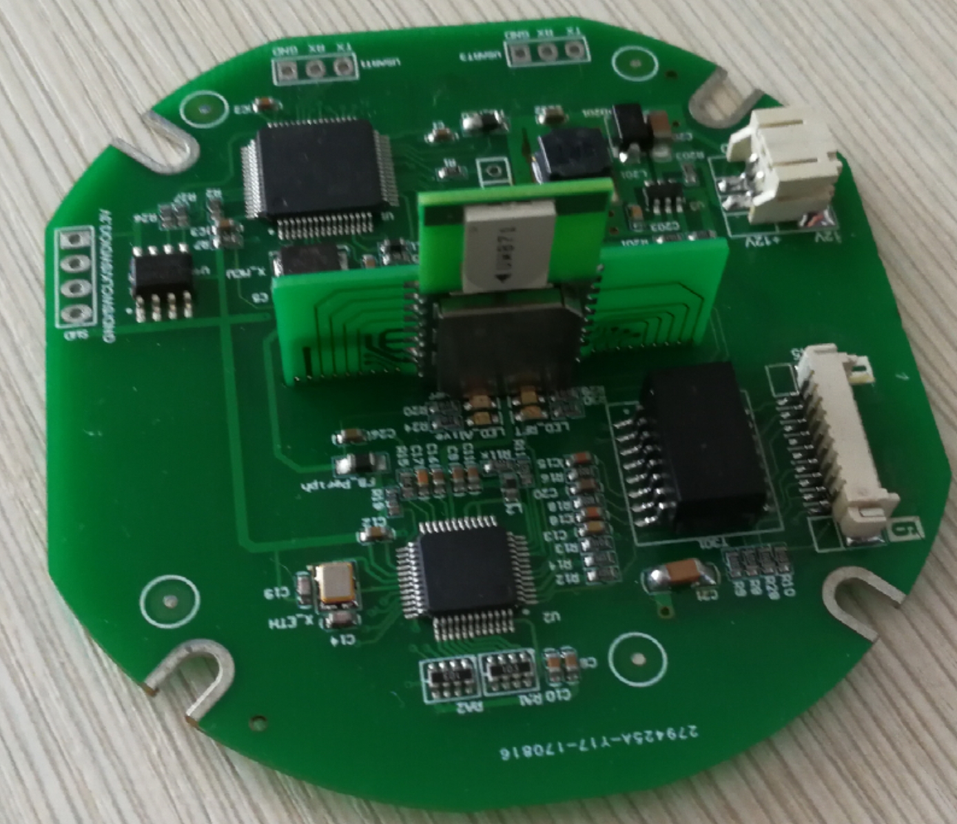
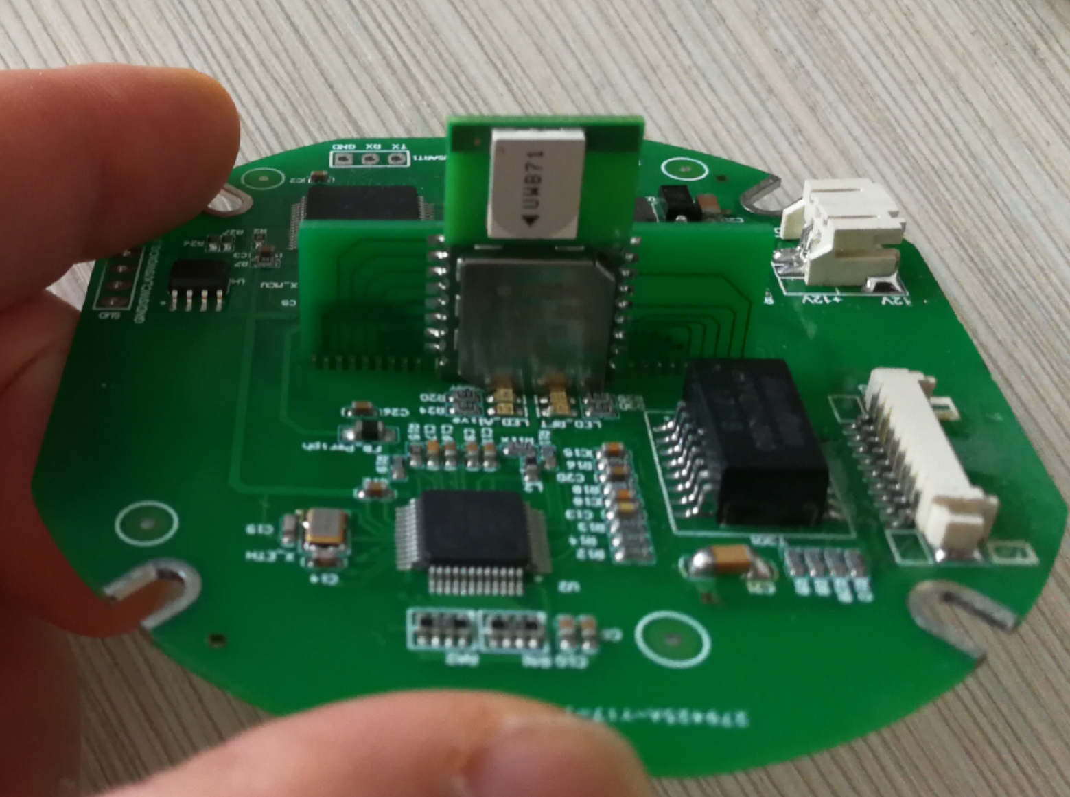
Below are photos of the finished anchor
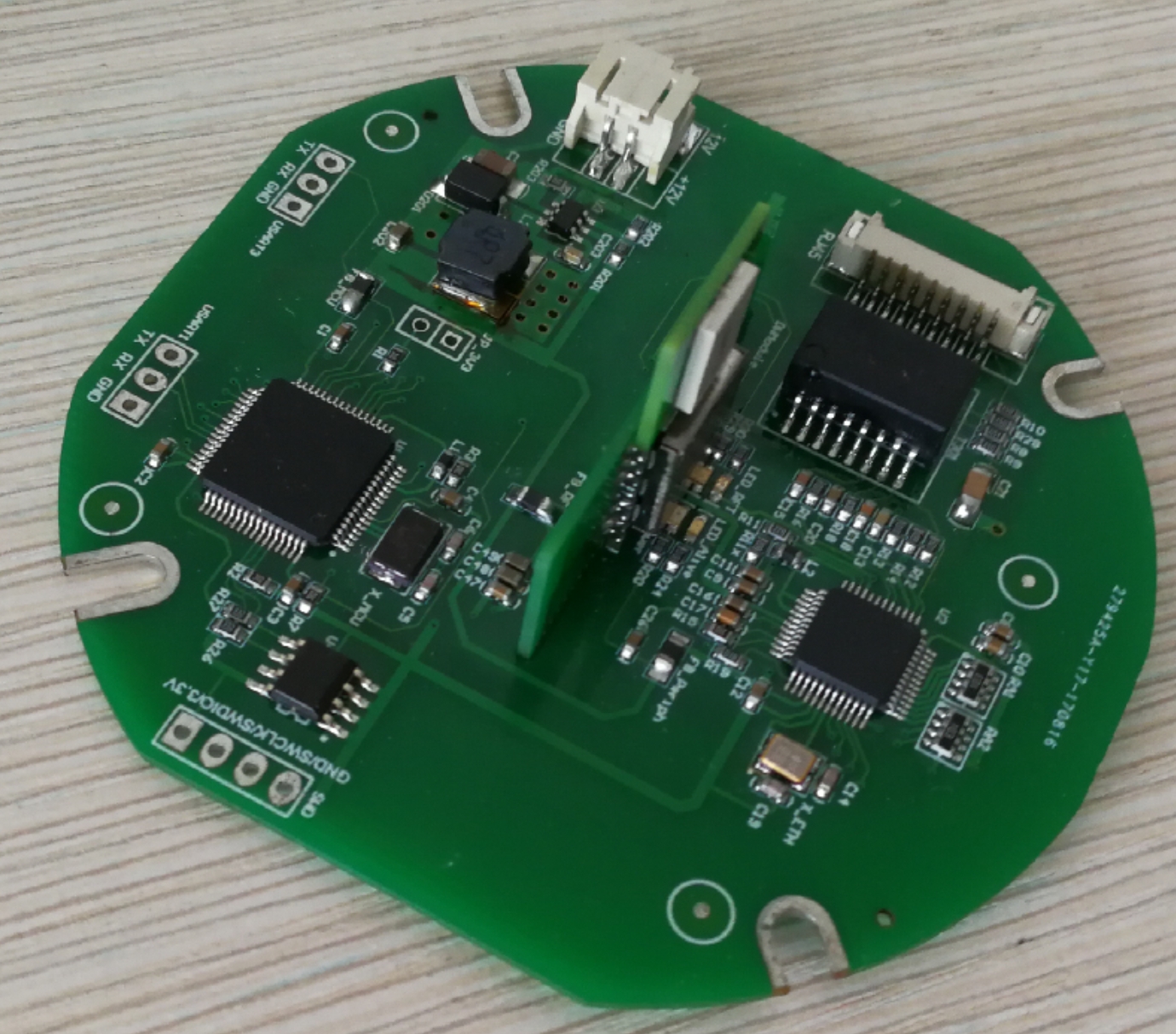
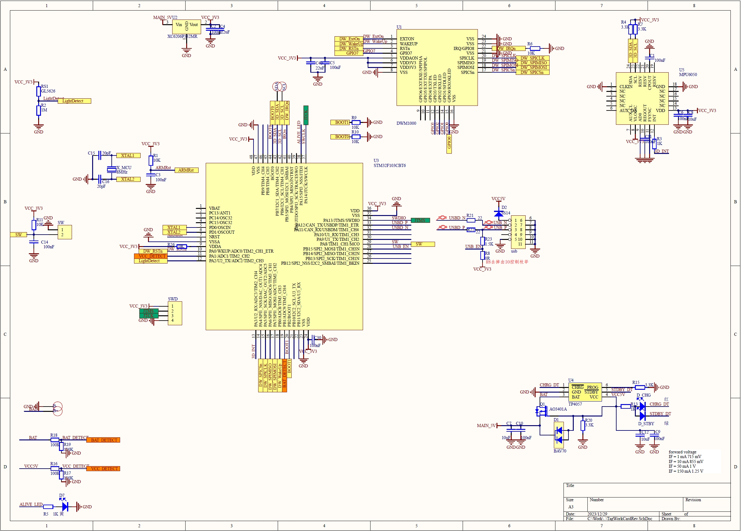
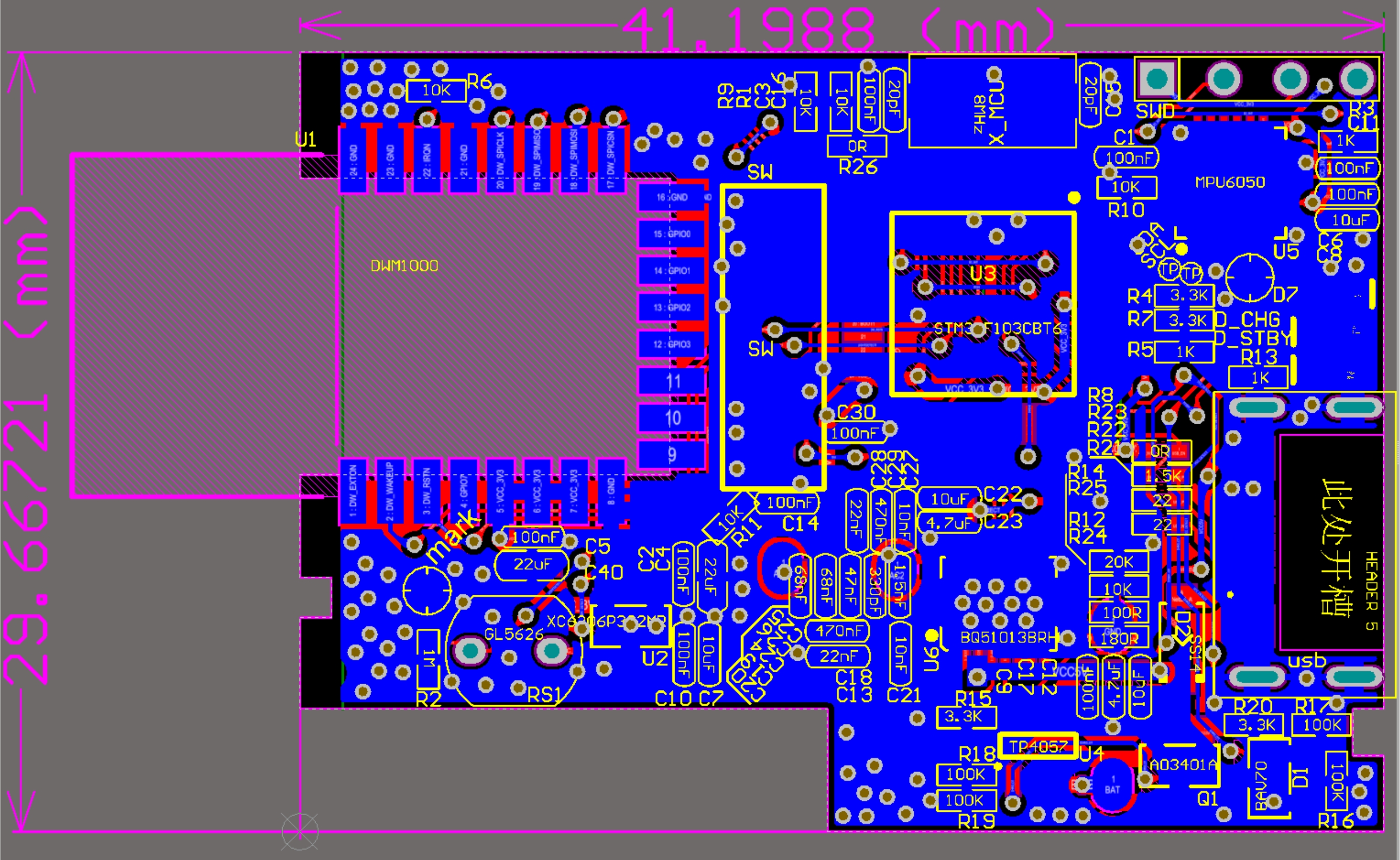
Please forgive me, I can't upload the AD project file of the anchor circuit, so I have to keep it for selling it. But I have included a high-definition picture of the anchor circuit, and you can draw a copy yourself.
A 24C64 is used in the circuit in order to preserve the anchor configuration. Later, the firmware used Flash to simulate EEPROM, and the 24C64 was cancelled.
If you are doing DIY, you don't need to make the board very small. The casing is a must! DW1000 and crystal oscillator are very sensitive to temperature. We have tested that if someone passes by the bare board without a casing, it will cause the DW1000 clock to change greatly.
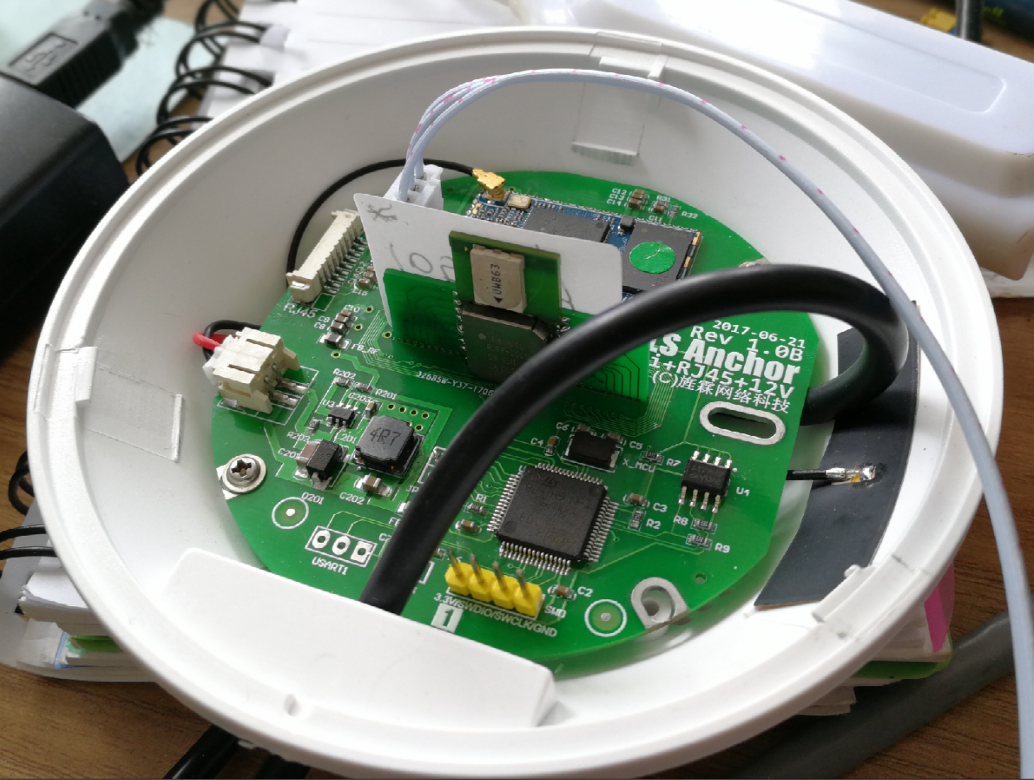
Here is another photo of our latest version of the mass-produced anchor for everyone to appreciate. It is powered by POE, has dual network ports, and integrates a network switch chip. Multiple anchors can be cascaded hand in hand.
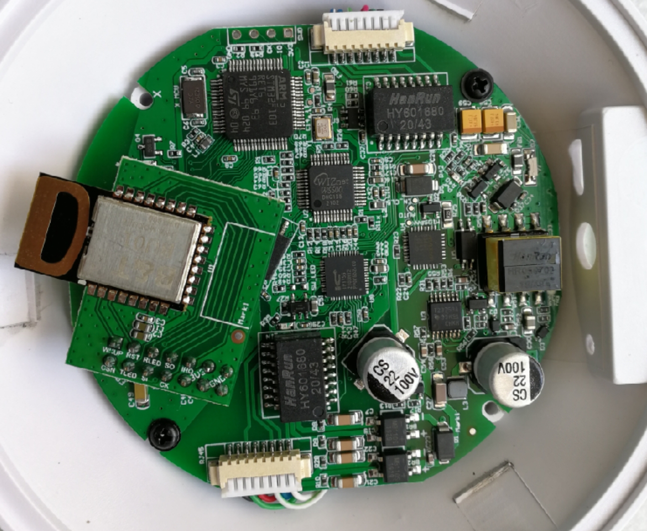
With this level of integration of the anchor, it can only be mounted by machine. If welded by hand, it is a very difficult job.
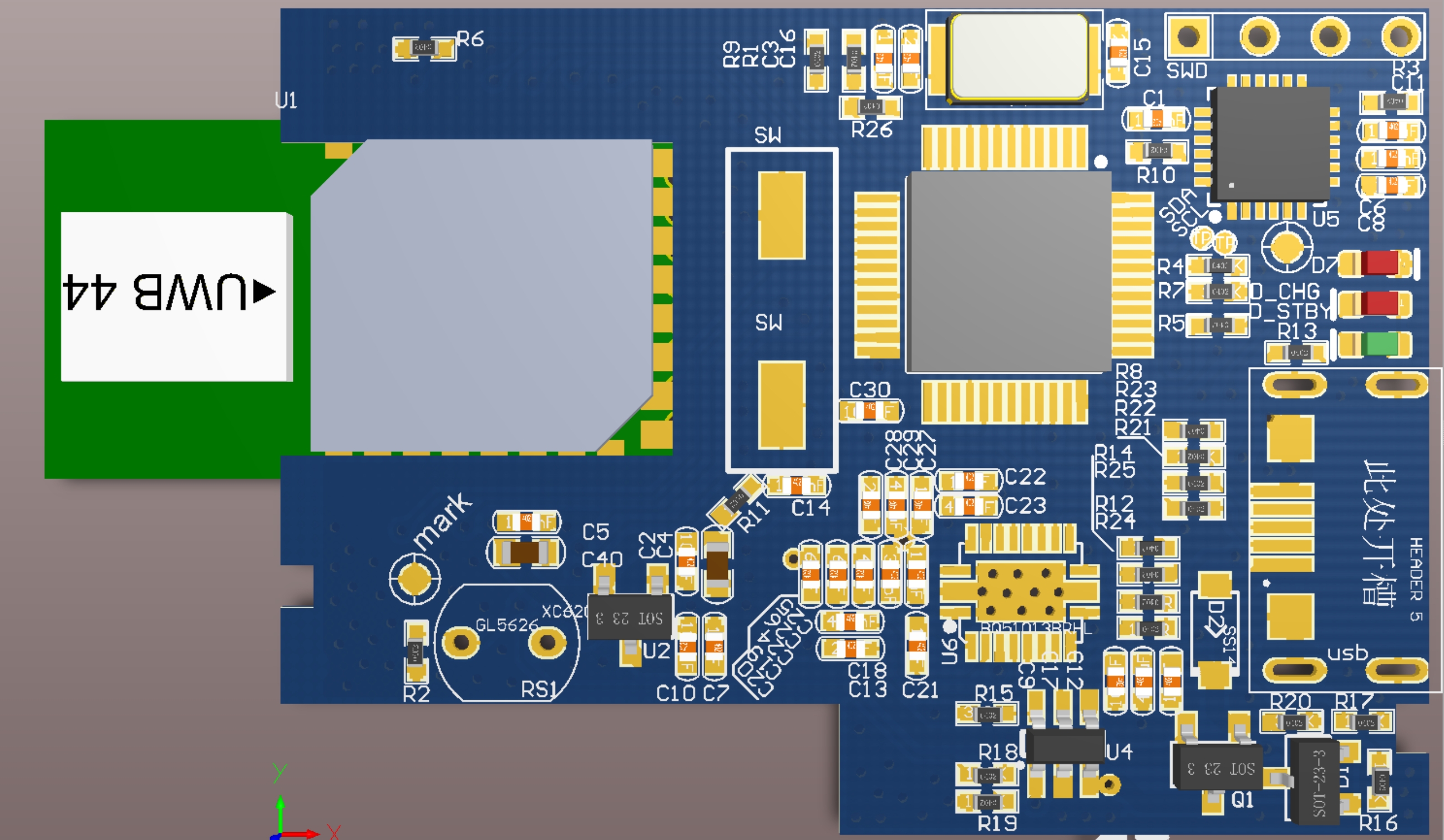
Tag Hardware Design
We use the name-card style tags, which can be used in a wider range of applications. In fact, many end users use name-card style tags, and the response during use is good.
The tag's MCU uses STM32F103CBT6, which has a smaller chip area and smaller RAM and Flash. In fact, we wanted to use STM32F10C8T6 at first, but later we found that Flash was too small.
Because we want to support online firmware upgrades, the Flash must be at least twice as large as the firmware, because in addition to the running firmware, space must be left for the newly uploaded firmware. Also leave some space for configuration parameters.
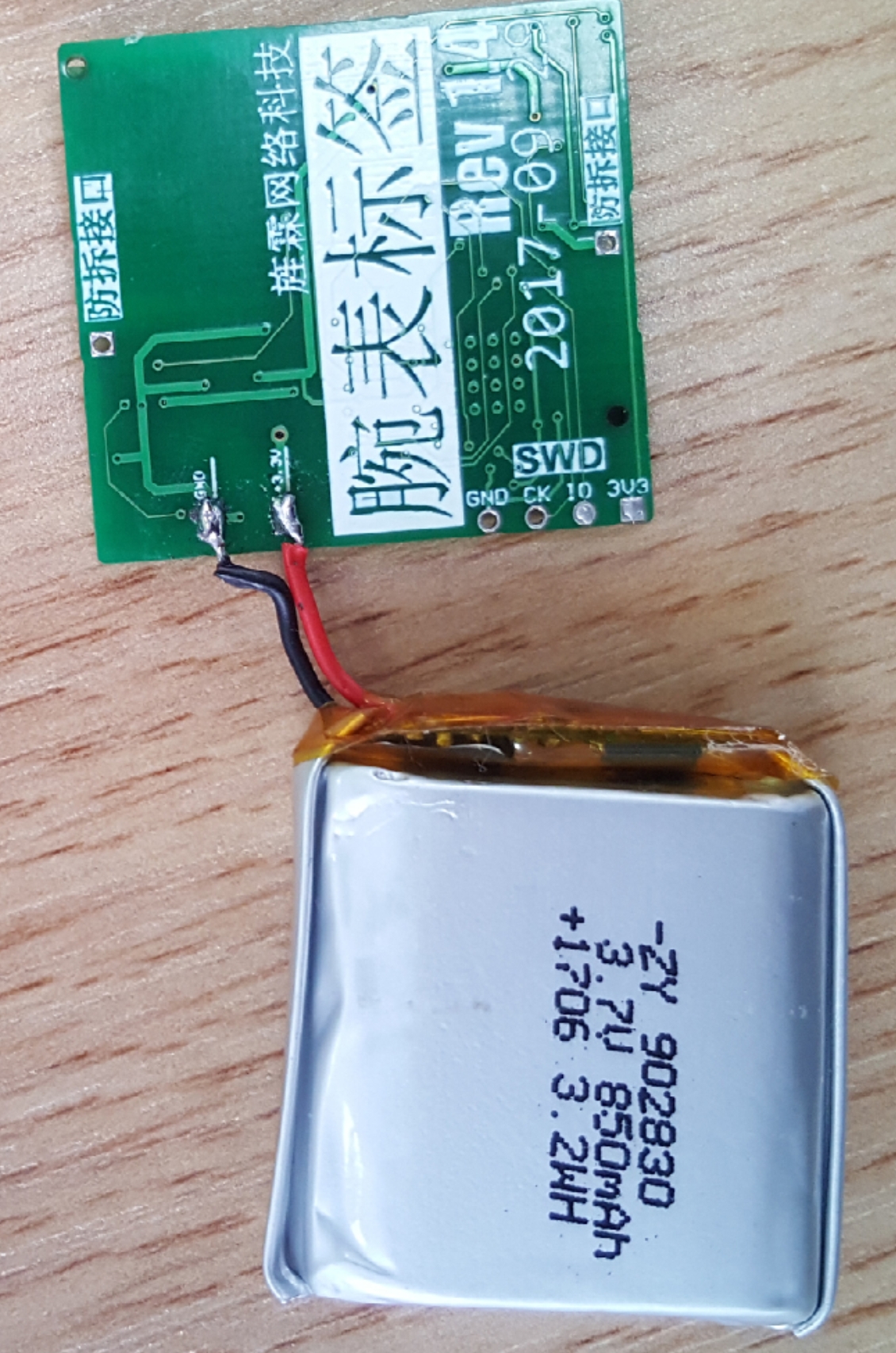
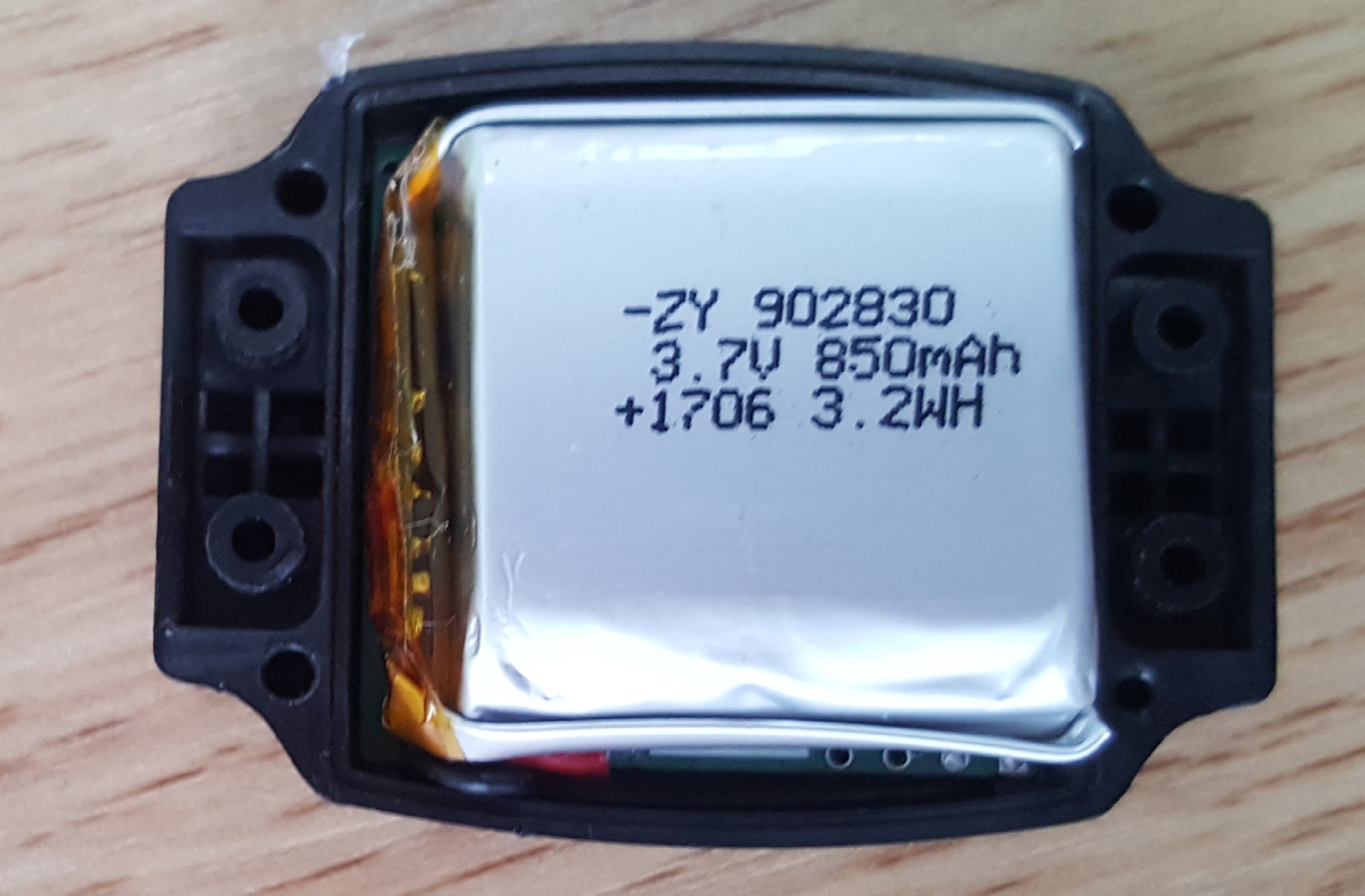
The tag uses an 800mah lithium polymer battery for power supply, and the charging chip uses TP4057. This charging chip is cheap and has a simple interface. Because of this, it is not a complete battery management chip, it only charges, and it charges in LDO mode.
During the charging process, the input DC 5V is converted into the 3.5V~4.2V required by the battery, and the energy between these two voltage differences becomes heat.
If the charging current is designed to be too large, it will be very hot; if the charging current is small, the charging time will be very long.
Later, I wanted to switch to a DC-DC charging chip, but the project was stopped, so I forgot about it. If a DC-DC charging chip is used, the heat generation will be much smaller, we can design the charging current to be larger, and charging will take much less time.
But the cost will increase a bit, and a large inductor may need to be added.
We also designed a wireless charging function. If you are just playing with it alone, you don't need to do this part. Wireless charging uses TI's BQ51013 chip. This chip supports the QI wireless charging standard.
With multiple uses in mind, tags add some small features:
- Photoresistor, used to detect ambient light brightness
- MPU6050 three-dimensional accelerometer
- Voltage divider resistor detects battery voltage
The driver of the MPU6050 was not ready, and other functions of the firmware were greatly affected, so we blocked it during mass production. Due to insufficient manpower and too many things to do, MPU6050 never had time to tinker with.
In the end, it was simply not attached and left empty on the board.
The voltage divider resistor detects the battery voltage and can roughly understand the remaining power. If possible, it is best to install a power detection chip. There should be a suitable power management chip now, a chip that integrates charging/discharging/power management.
At the beginning, in order to save power, we used 1M ohm voltage dividing resistors. Later, we found that this was not possible because there were discrete errors. Some boards can measure accurately, and some boards have large errors.
Because the ADC internal resistance of STM32 is not very large. Later we changed it to 100K euros and this problem was solved.
In the design of tags, low power consumption needs to be considered in many aspects, so as to save power consumption as much as possible and make the tag's standby time longer.
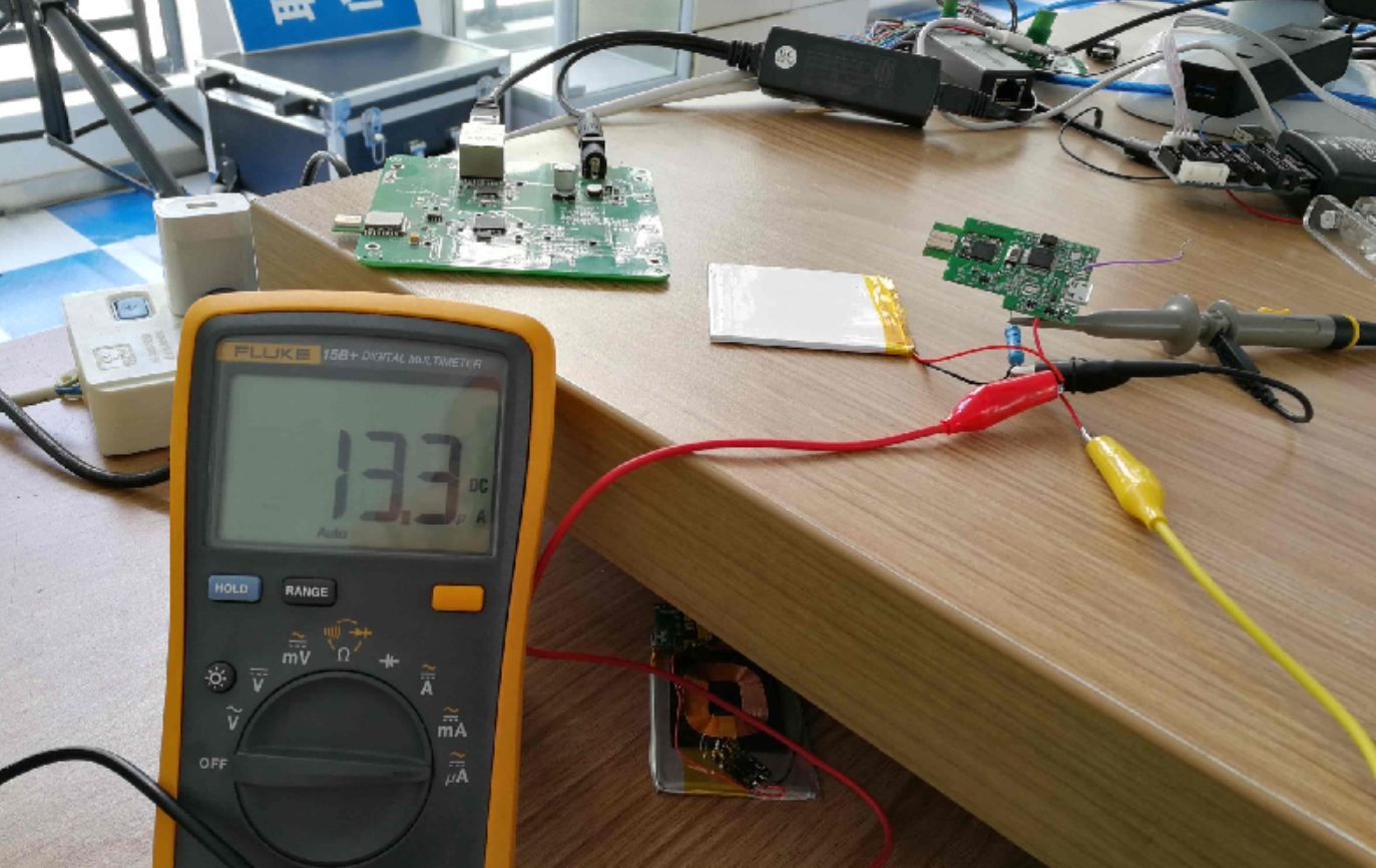
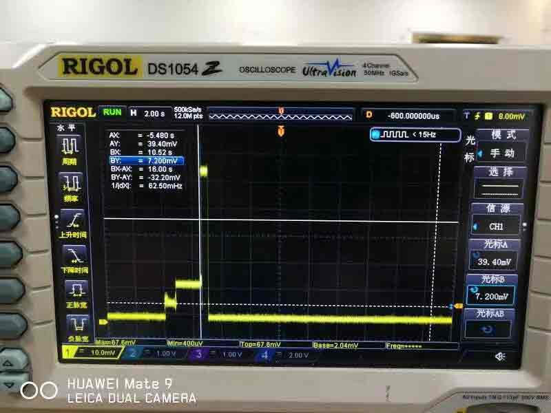
The lowest power consumption of the tag reaches 13.3uA, which is the current when the tag is in sleep state. We also used an oscilloscope to view the current draw during tag operation.
From the photos, you can clearly see several working processes of the tag: first it is in a sleep state, then the MCU wakes up and the current increases, the DW1000 wakes up and the current increases again, transmits UWB data packets (short time/high current), and sleeps again.
Here, the time between DW1000 waking up and launching is a bit long, which is waiting for DW1000 to enter a stable working state. It should be possible to shorten this wait and save some power.
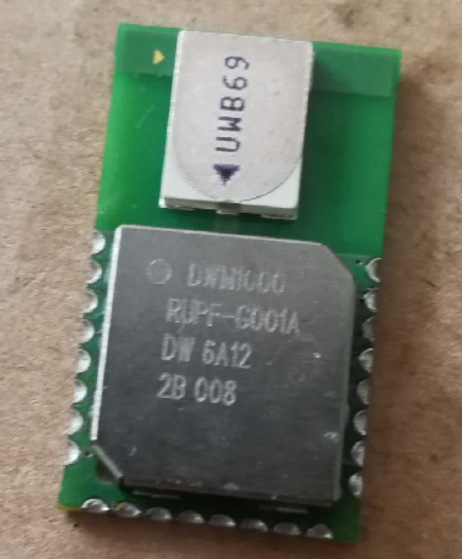
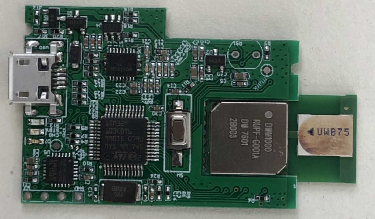
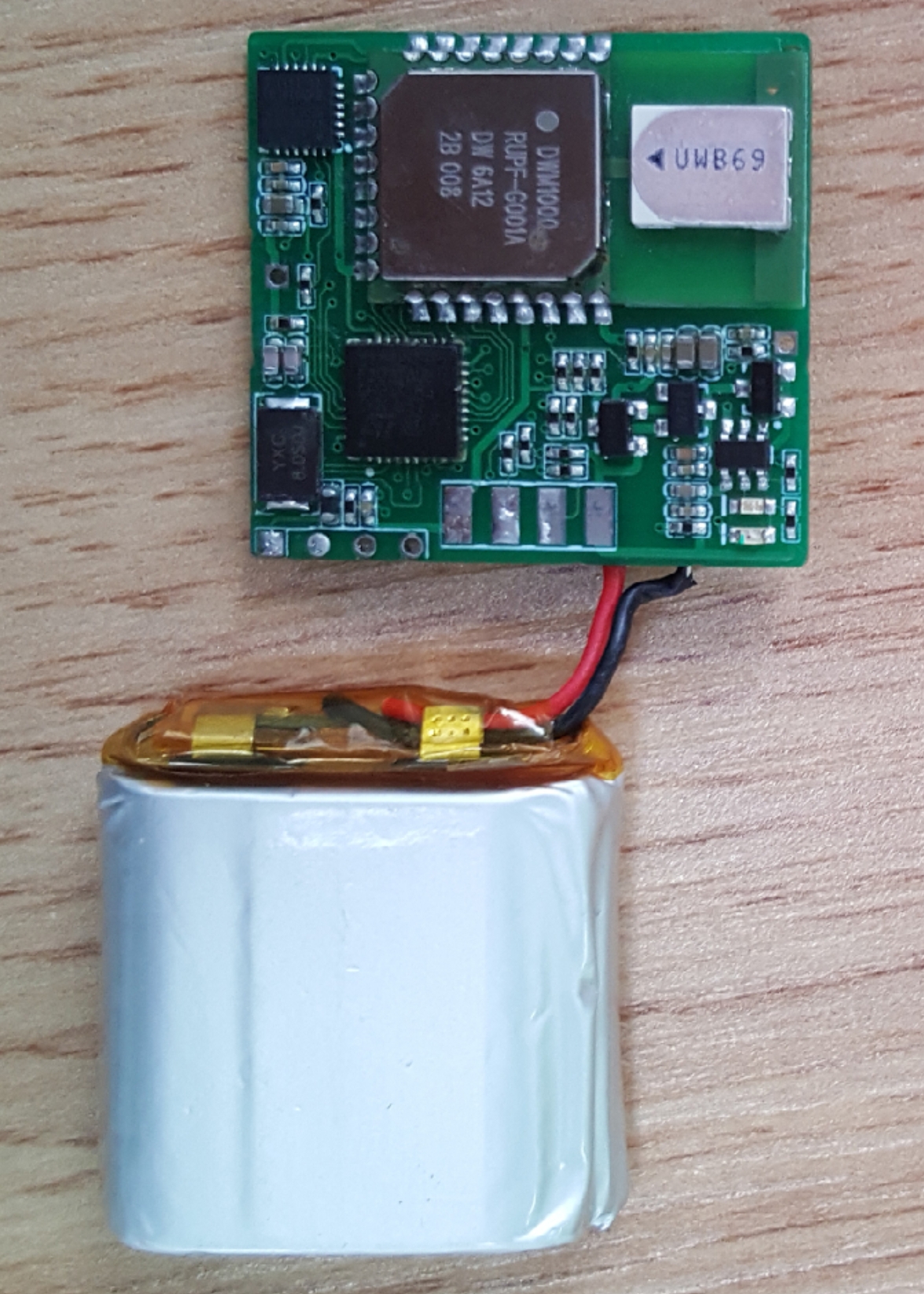
It is also worth mentioning that because the name-card style tag is very thin, in order to save space, the DWM1000 is welded from the back. If you solder from the front, the PCBA should be higher.
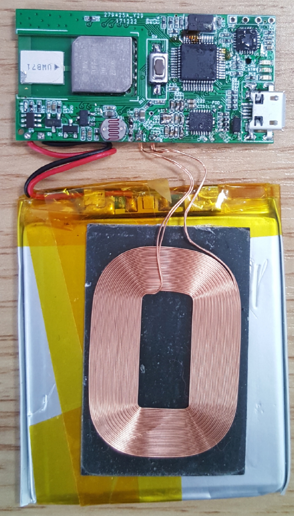
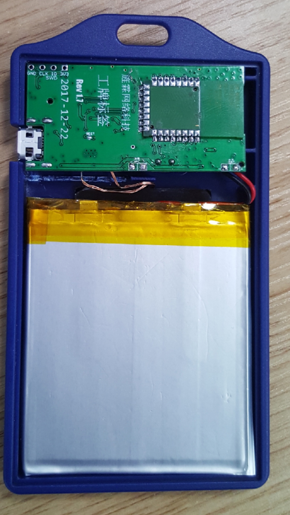
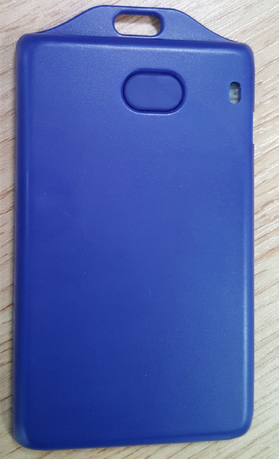
Our name-card style tag has been revised dozens of times, and each time there will be some slight differences, but the basic circuit remains the same. These photos are for your reference.
The tag can also be made into a bracelet style.
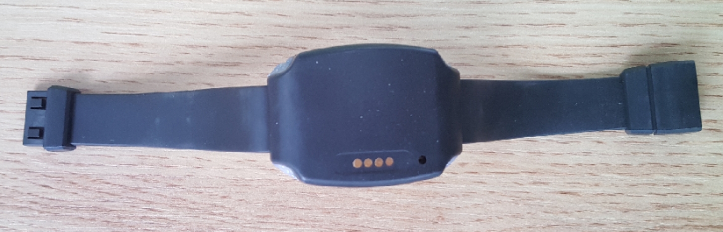
We give customers OEM tags and install them on the car.
Anyway, the basic circuit is still the same. Therefore, after the firmware is written, it is basically compatible. One firmware is compatible with the tags of all models.
A customer wants to make a bracelet tag with a display. He plans to add OLED to display the time and some received messages, and also add a vibration motor. After some research, I found that STM32F103 is not enough.
To display messages, there must be Chinese characters, and then a Chinese character library must be obtained. The small Flash of STM32 will definitely not be able to fit it. The large Flash version of STM32 is difficult to buy and expensive.
I plan to use ESP32 as an MCU, and I can also add WiFi and Bluetooth support. Later, the client's project was stopped, and later, our project was also stopped, and we stopped working on it.
If you are using it commercially, it is recommended to use ESP32 as the MCU. It is best to replace the MCU of the anchor/tag with ESP32. In this way, they can be unified and the code can be reused. ESP32 is cheap and performs well, which is really a good thing.
This website is our home base, and this series of articles will be updated from time to time. In addition to this site, this series of articles is also published on Zhihu , cnBlogs , CSDN and other websites.
By the way, I'm looking for a job. Due to business reasons, the company was dissolved. I have 30+ years of work experience, 20+ years of experience in C/C++/Java/Delphi, and a little bit of Javascript/Python/Lua.
In 199x, I wrote a Chinese character system in x86 assembly, and later used Delphi to write a mail server. I have written countless application systems, and the code I have written should exceed 2 million lines.
10+ years of hardware design experience, designing multiple embedded products. In the early stages of this UWB location system, the hardware and software were all developed by me alone, and the team was only built later. Base Guiyang, China, or remotely.
If there are job opportunities, please contact me (