Hardware Design for Location Tags
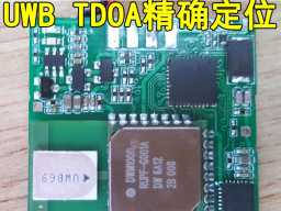
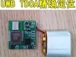
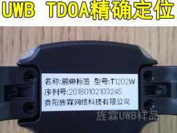
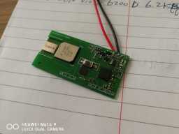
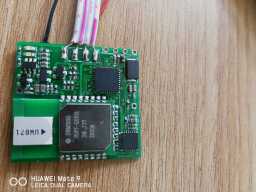
Our mass-produced location tags are name-card style and use DW1000 as the UWB transceiver. In the early stage, the DWM1000 module was used, and in the later stage, the self-designed UWB module was used. Some models also added LNA/PA to increase the location range.
Use STM32F103RBT6 as the main control MCU. Our initial purchase price for this chip was about 12 yuan to 14 yuan, and later it rose to 180 yuan per piece. It was really crazy and made us very passive. However, it later fell back.
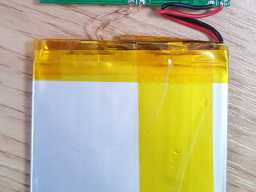
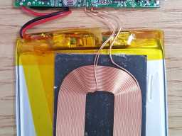
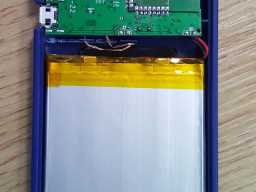
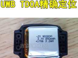
The power supply uses an 800mah lithium battery as the power source, and uses a USB interface for charging, which also serves as the tag configuration interface.
There is an MPU6050 three-dimensional accelerometer chip designed on the tag. During mass production, it was found that the effect was not very great, and this chip was not attached in the later production.
There are 2 LEDs designed on the tag, one red and one green.
There is a button designed on the tag, which can be used for alarm purposes. Specific uses require server-side design. The firmware design can support multiple buttons, and later OEM customers need to add other functions (such as anti-tampering, etc.).
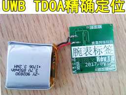
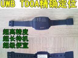
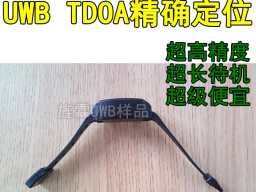
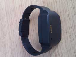
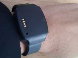
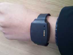
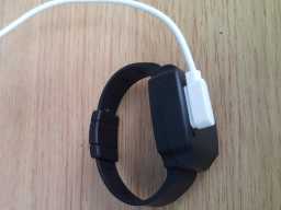
We also designed a bracelet (watch) style location tag. In order to reduce the size, the MCU uses the VFN package version of the STM32F103RB series. This bracelet is only a prototype and has not been mass-produced.
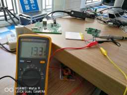
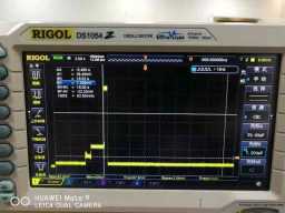
We achieve a minimum power consumption of 13.3uA during sleep mode.
Through the oscilloscope, we can clearly see several working stages of the tag: it usually consumes almost no power when sleeping, starts to consume more power when awakened, further increases during the initialization phase, consumes the highest power when transmitting data packets, and then goes to sleep again.
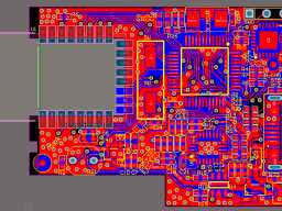
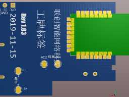
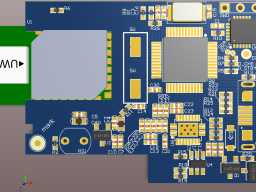
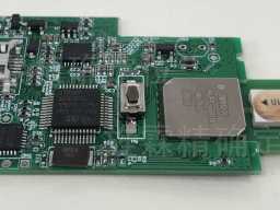
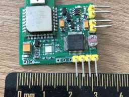
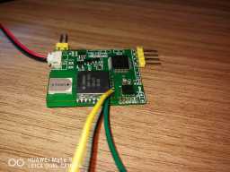
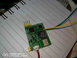
The following pictures show several tag PCBs designed during the research and development process.
